
Catalyst layer and preparation process thereof, and membrane-electrode assembly and polymer electrolyte fuel cell using the catalyst layer

a catalyst layer and membrane electrolyte technology, applied in the direction of organic compound/hydride/coordination complex catalysts, physical/chemical process catalysts, cell components, etc., can solve the problems of difficult to ensure sufficient operation time, hard for such particles to contribute to the reaction, and inability to contribute to electrode reaction, etc., to achieve excellent electrode reaction efficiency, improve cell efficiency, and reduce the amount of noble metal catalysts used

Inactive Publication Date: 2013-04-16
KURARAY CO LTD
View PDF20 Cites 1 Cited by
  • Summary
  • Abstract
  • Description
  • Claims
  • Application Information

AI Technical Summary

Benefits of technology

[0030]The catalyst layer, membrane-electrode assembly and polymer electrolyte fuel cell of the invention are economical, environment-friendly and excellent in electrode reaction efficiency, and are useful for improvement of cell efficiency or reduce of use amount of noble metal catalysts used in cells.

Problems solved by technology

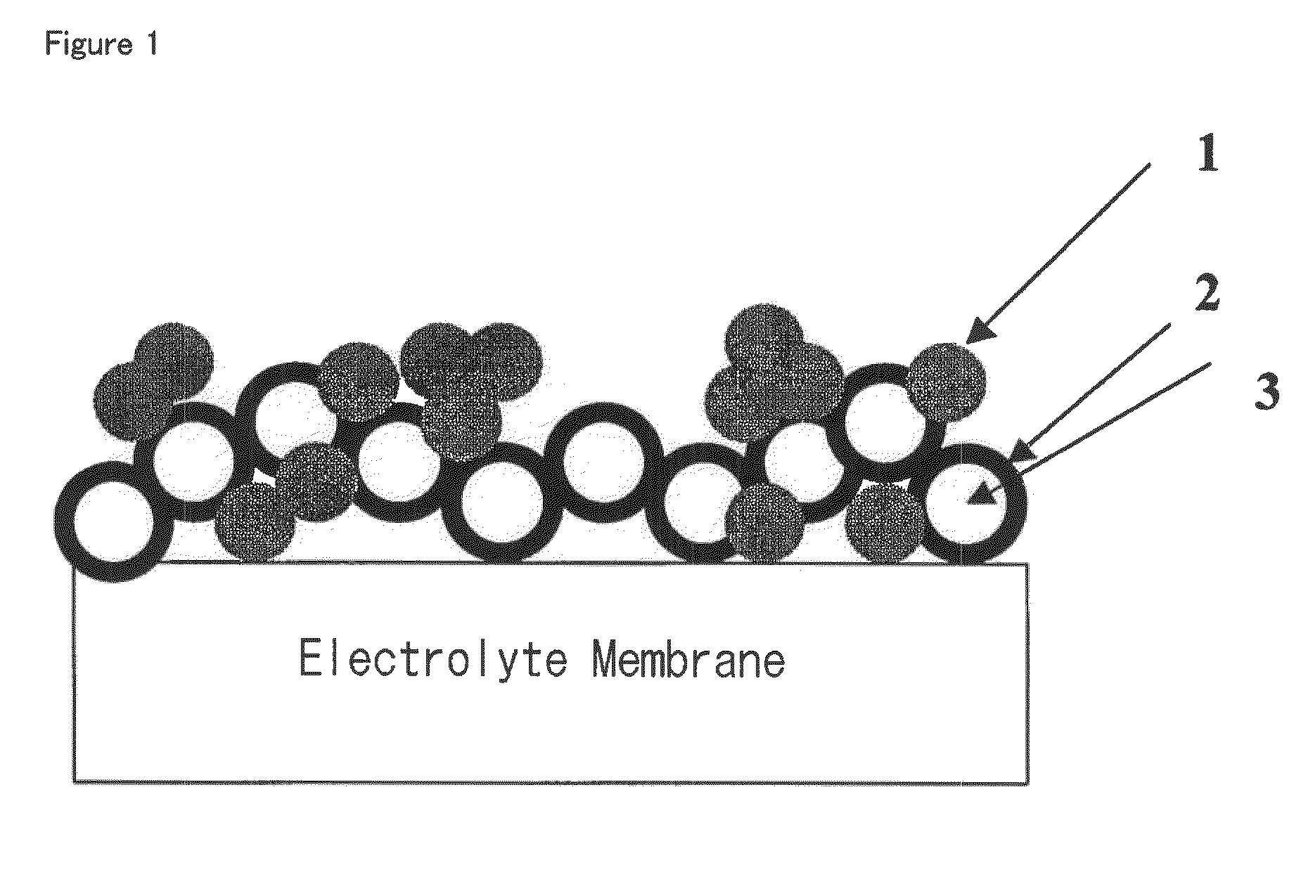
Therefore, catalyst particles not contacting with the ion path formed by the ion-conductive binder cannot take part in the formation of the three-phase boundary, and it is hard for such particles to contribute to the reaction.
However, Nafion has a hydrophobic main chain having no sulfonic acid group, and it is supposed that the catalyst covered with the hydrophobic part in the catalyst layer cannot form a three-phase interface and cannot contribute to electrode reaction.
If the content of sulfonic acid groups is increased for increasing the number of the three-phase interface and increasing catalyst utilization proportion, there is an apprehension that the hydrophilicity of the polymer is heightened, the binder itself is gradually eluted out of the cell system by moisture contained in reaction gases, water formed in the oxygen electrode, etc. during power generation, and deterioration of the electrodes advances to make ensuring of sufficient operation time impossible.
If the Nafion content is increased for increasing the content of sulfonic acid groups in the catalyst layer, there is an apprehension that Nafion blocks the diffusion paths of reactants necessary for formation of the three-phase interfaces to lower the efficiency of electrode reaction.
Such an electrode is advantageous for forming diffusion paths of reactant gases, but since the particle size of the resulting particles is as very large as 3 to 20 μm, it is difficult to design minute electrode catalyst layers for increasing three-phase interfaces.
Furthermore, since the matrix polymer is used as the electrolyte particles, it is impossible to heighten the ionic group density of electrolyte particle surfaces and it is difficult to form ion paths necessary for formation of three-phase interfaces.
However, ion-conductive binders comprising the above-mentioned aromatic engineering plastic resin or styrene type thermoplastic elastomer also have the same problems as fluorine-containing ion-conductive binders.
Further, resins are studied which have a high ionic group content and are made to be insoluble in water by introducing cross-linking groups, but the resins are insoluble in organic solvents and need to be used as a suspension in a suitable solvent, and moreover, are poor in dispersibility into the catalyst layer and thus it is difficult to form effective three-phase interfaces.
However, the above-mentioned anion-conductive binders also have the same defects as the cation-conductive binders have.

Method used


Image

  • Catalyst layer and preparation process thereof, and membrane-electrode assembly and polymer electrolyte fuel cell using the catalyst layer
  • Catalyst layer and preparation process thereof, and membrane-electrode assembly and polymer electrolyte fuel cell using the catalyst layer
  • Catalyst layer and preparation process thereof, and membrane-electrode assembly and polymer electrolyte fuel cell using the catalyst layer

Examples


referential example 1

Preparation of a block copolymer composed of poly (α-methylstyrene) Block (Polymer Block (A)) and Hydrogenated Polybutadiene Block (Polymer Block (B))

[0083]In a similar process to a previously reported process (WO 02 / 40611 A), a poly (α-methylstyrene)-b-polybutadiene-b-poly (α-methylstyrene) triblock copolymer (hereinafter abbreviated as mSEBmS) was synthesized. The number average molecular weight (GPC measurement, in terms of polystyrene) of the resulting mSEBmS was 76,000, and the amount of the 1,4-bond determined by 1H-NMR measurement was 55% and the content of the α-methylstyrene unit also determined by the 1H-NMR measurement was 30.0% by mass. Further, it was revealed by composition analysis through 1H-NMR spectrum measurement that α-methylstyrene was not substantially copolymerized into the polybutadiene block.

[0084]A solution of the synthesized mSEBmS in cyclohexane was prepared, the solution was put in a pressure proof vessel whose atmosphere had sufficiently been replaced w...

referential example 2

Preparation of a Block Copolymer Composed of Polystyrene (Polymer Block (A)), Hydrogenated Polyisoprene (Polymer Block (B1)) and Poly (Tert-Butylstyrene) (Polymer Block (B2))

[0085]The block copolymer was synthesized in a similar process to a previously reported process (JP 2006-49002 A). Namely, after 568 ml of dehydrated cyclohexane and 1.14 ml of sec-butyllithium (1.3M-cyclohexane solution) were put in a 1,000-ml egg-plant type flask, 4.27 ml of styrene, 53.3 ml of 4-tert-butylstyrene, 66.4 ml of isoprene, 52.6 ml of 4-tert-butylstyrene and 9.30 ml of styrene were added successively and polymerized respectively at 60° C. to synthesize polystyrene-b-poly(4-tert-butylstyrene)-b-polyisoprene-b-poly(4-tert-butylstyrene)-b-polystyrene (hereinafter, abbreviated as StBSItBSS). The number average molecular weight (GPC measurement, in terms of polystyrene) of the obtained StBSItBSS was 167,471, the amount of the 1,4-bond, the content of the styrene unit and the content of the 4-tert-butyls...

example 1

(1) Synthesis of Sulfonated HmSEBmS

[0087]A sulfonating reagent was prepared by reacting 49.5 ml of acetic anhydride with 22.1 ml of sulfuric acid at 0° C. in 99.0 ml of methylene chloride. Separately, 100 g of the block copolymer HmSEBmS obtained in Referential example 1 was vacuum dried for 1 hour in a glass-made reaction vessel equipped with a stirrer, the inside atmosphere of the reaction vessel was replaced with nitrogen, 1,000 ml of methylene chloride was added, and the mixture was stirred at 35° C. for 4 hours to dissolve the block copolymer. After the dissolution, the sulfonating reagent was gradually added dropwise thereto over a period of 20 minutes. After stirring at 35° C. for 6 hours, the polymer solution was poured into 2 L of distilled water under stirring to coagulate and deposit the polymer. The deposited solid matter was washed with distilled water of 90° C. for 30 minutes, and then filtered. This operation of washing and filtration was repeated until the pH of the ...


PUM

PropertyMeasurementUnit
particle sizeaaaaaaaaaa

Abstract

In a membrane-electrode assembly for polymer electrolyte fuel cells comprising a polymer electrolyte membrane and two gas diffusion electrodes being bonded to the membrane so that the membrane can be between them, at least one catalyst layer constituting the gas diffusion electrodes characterized in that the ion-conductive binder comprises a block copolymer having a particle size of 1 μm or less comprising a polymer block (A) having ion-conductive groups and a polymer block (B) having no ion-conductive group, both polymer blocks phase separate from each other, polymer block (A) forms a continuous phase, and the contact parts of the block copolymer with catalyst particles are comprised of polymer block (A) having ion-conductive groups; a membrane-electrode assembly and a polymer electrolyte fuel cell.

Description

TECHNICAL FIELD[0001]This invention relates to a catalyst layer and a preparation process thereof and a membrane-electrode assembly and a polymer electrolyte fuel cell using the catalyst layer.BACKGROUND ART[0002]In recent years, as a power generation system which is mild to the global environment and clean, fuel cells have drawn attention. Fuel cells are classified, depending on kinds of electrolytes, into a phosphoric acid type, a molten carbonate type, a solid oxide type, a polymer electrolyte type, etc. Among them, polymer electrolyte fuel cells are tried to be applied as power sources for electric vehicles, power sources for portable apparatuses, and, further, applied to domestic cogeneration systems utilizing electricity and heat at the same time, from the viewpoints of workability at low temperatures, miniaturization and lightening, etc.[0003]A polymer electrolyte fuel cell is generally composed as follows. First, on both sides of a polymer electrolyte membrane having ion con...

Claims


Application Information

Patent Timeline
Patent Type & Authority Patents(United States)
IPC IPC(8): H01M4/60
CPCH01M4/8605H01M4/8668Y02E60/50H01M8/1004H01M4/88H01M4/90H01M8/10
Inventor NAKAI, SHINJIKUBO, KEIJIOHGI, HIROYUKIONO, TOMOHIRO
Owner KURARAY CO LTD
Learn More