Coatings, composition, and method related to non-spalling low density hardface coatings

a low density, hard coating technology, applied in the direction of natural mineral layered products, water-setting substance layered products, transportation and packaging, etc., can solve the problems of thermally sprayed tungsten carbide-cobalt coatings, for example, being very hard, brittle and dense, and ceramics generally decompose instead of melting

Active Publication Date: 2013-06-11
HYBRID MATERIALS LLC
View PDF8 Cites 8 Cited by
  • Summary
  • Abstract
  • Description
  • Claims
  • Application Information

AI Technical Summary

Benefits of technology

[0013]The present invention has been developed in response to the current state of the art, and in particular, in response to these and other problems and needs that have not been fully or completely solved by currently available expedients. Thus, it is an overall object of the present invention to effectively resolve at least the problems and shortcomings identified herein. Embodiments of the present invention are particularly suitable for use as hardfacings in aerospace structural elements where ruggedness, reliability, durability, and low density are significant factors for functionality and safety.
[0015]Although capable of standing alone without a substrate, in certain embodiments, the composite body is bonded to a substrate such as, for example, steel, titanium, aluminum, or their alloys, particularly their high strength alloys. Such substrates are typically metals that require a hardfacing for purposes of wear, ruggedness, corrosion resistance, and durability.

Problems solved by technology

Hardface coatings, particularly chromium and tungsten based coatings formed by the thermal spraying of composite powders are well known, but they are generally prone to spalling, and they are heavy.
Thermally sprayed tungsten carbide-cobalt coatings, for example, are very hard, brittle and dense.
The formation of coatings by thermal spraying ceramics such as ceramic nitrides had been proposed, but ceramics generally decompose instead of melting.
Thermal spraying operations are typically carried out at temperatures well in excess of 1900 degrees centigrade, so attempts to form coatings by thermal spraying ceramic nitrides had generally been unsuccessful.
The application of ceramic nitrides via physical vapor deposition and chemical vapor deposition operations for forming coatings that control wear and friction had been previously proposed, but such vapor deposition operations tended to be slow and expensive.
Previous attempts to improve wear had typically involved making harder and stiffer coatings at the expense of ductility.
In general, as the coatings became harder and stiffer, the occurrence of spalling increased.
Unfortunately, these thermally sprayed coatings, which because of having high hardness, are brittle and are subject to spelling and catastrophic failure when subjected to impacts, point loading, or other high stress situations such as those that exist in landing gear cylinders used in carrier based aircraft.
These higher density coatings add substantial weight, have low throughput through HVOF gun systems, and impose significant penalties in fuel economy and payload for aircraft and other transportation systems.
Due to their brittleness and high modulus, they are extremely sensitive to flaws and defects on the surface, and in the coating, meaning they are very difficult to apply, limiting their utility and the number of qualified applicators.
Such structural members tended to flex and deform.
This resulted in spalling of the hardface coatings.
The formation of a ductile hardface coating previously appeared to be unachievable.
Hardness and ductility were generally believed to be unachievable in the same coating.

Method used


Image

  • Coatings, composition, and method related to non-spalling low density hardface coatings
  • Coatings, composition, and method related to non-spalling low density hardface coatings
  • Coatings, composition, and method related to non-spalling low density hardface coatings

Examples


example 1

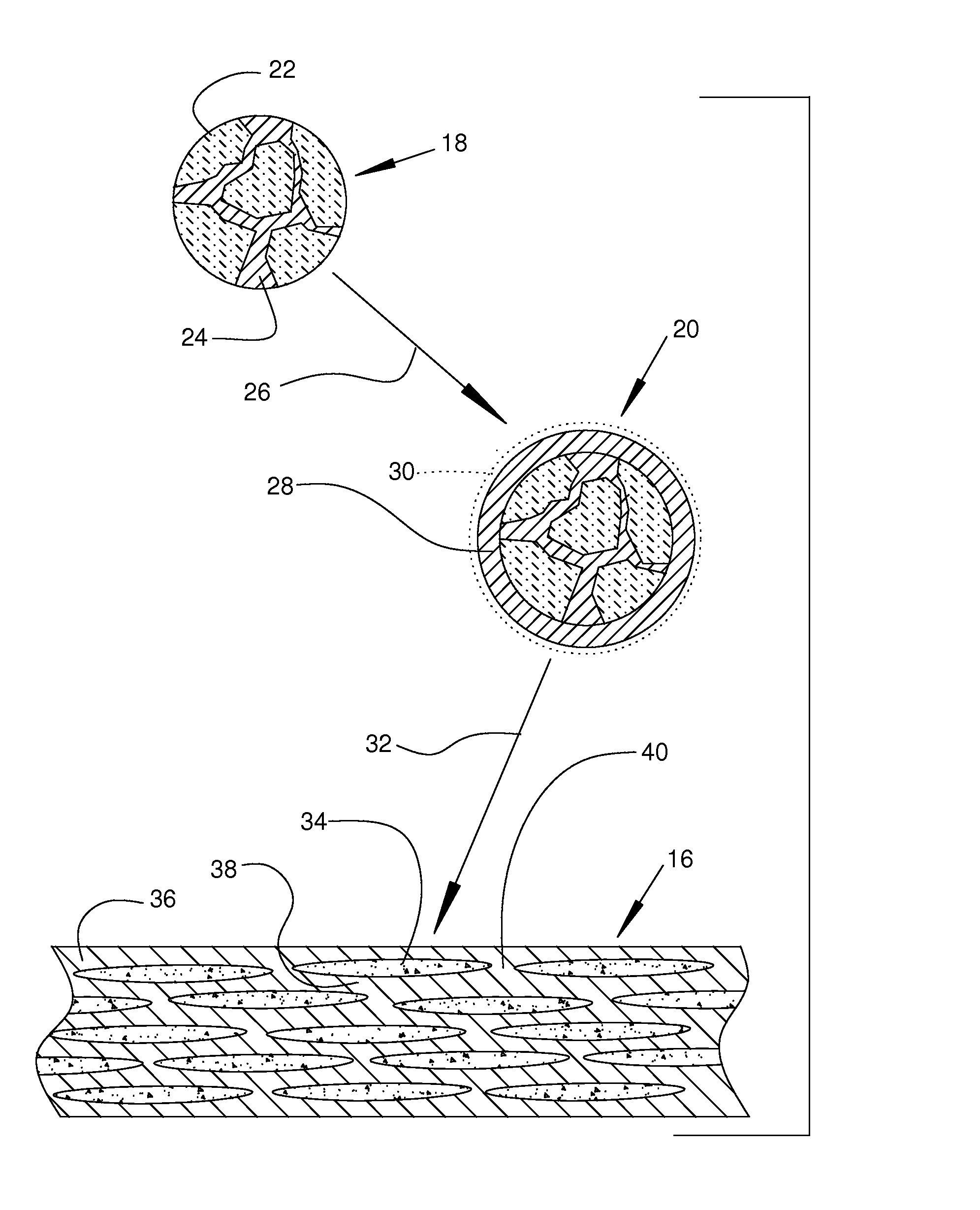
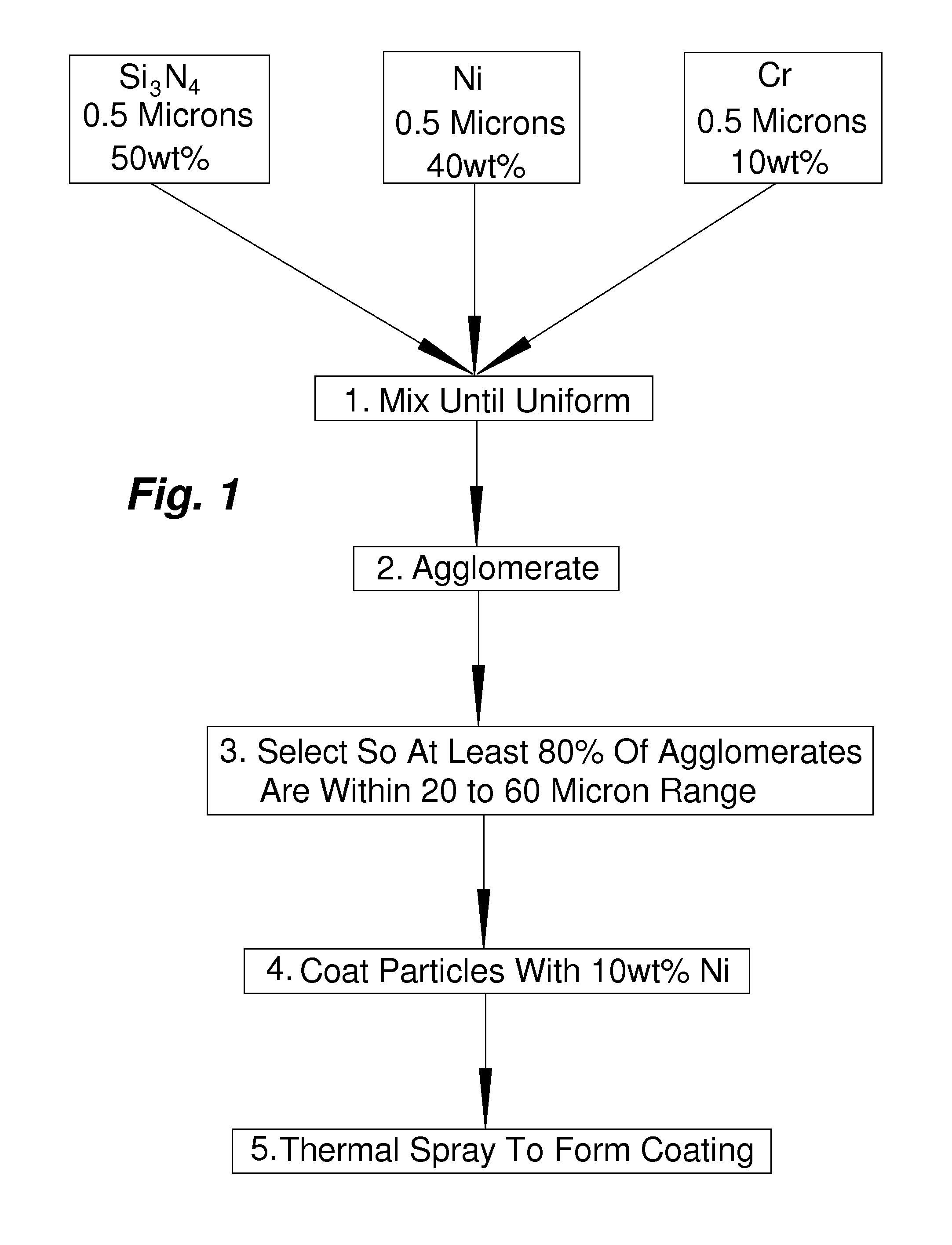
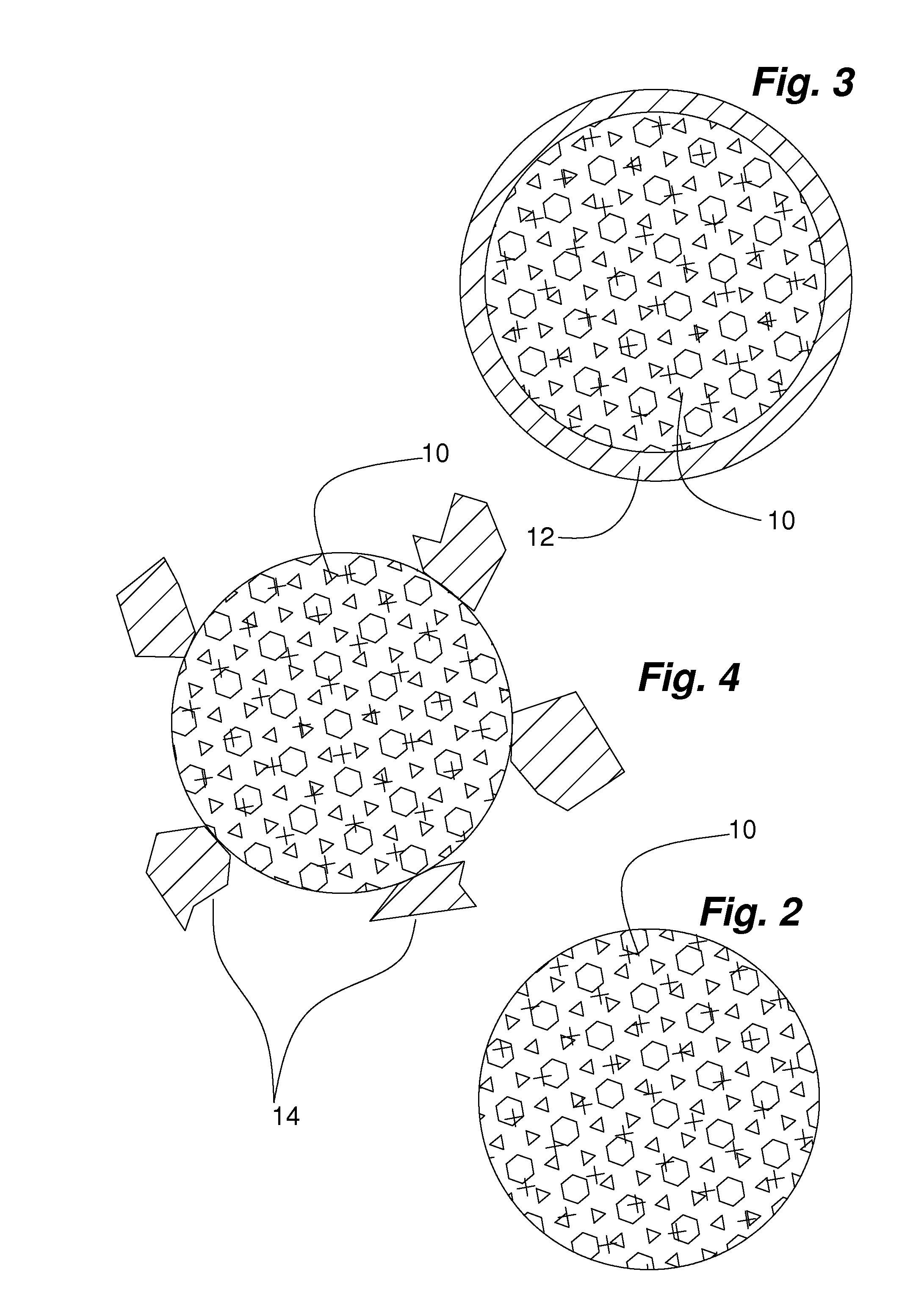
[0039]An agglomerated microcomposite powder was prepared by ball milling 0.5 micron Si3N4 powders with 40 weight percent (wt %) Ni and 10 wt % Cr powder for 24 hours in a ball mill. This Example is diagrammatically illustrated in FIG. 1. A polyvinyl alcohol binder was added along with water and conventional surfactants to reduce the viscosity of the resulting slurry to between 200 and 300 centipoises. An agglomerated powder was formed by spray drying the slurry. The slurry was spray dried at 15,000 revolutions per minute using a centrifugal atomizer, a gas temperature of 300 degrees centigrade, and an exit temperature of 180 degrees Fahrenheit to create approximately spherical, free flowing agglomerated powders. These powders were debound at 200 to 300 degrees centigrade in hydrogen, and sintered for 2 hours at 1250 degrees centigrade to produce a densified, free flowing powder wherein approximately half of the particles had a diameter of approximately 38 microns. The powders were s...

example 2

[0040]Titanium nitride powder having an average particle size of about 1 to 3 microns (manufactured by Kennametal inc) was mechanically alloyed with 32 wt % Ni and 8 wt % Cr powder (average particle size of about 1 to 5 microns) in a Segvari type attrition mill for 24 hours. The attrition mill was manufactured by Union Process. All powders were −325 mesh. The mechanically allowed powders were removed from the mill, dried, and then blended using a high shear mixer with a water-2 percent polyvinyl alcohol solution basified with NH3OH to produce about a 45 volume percent (V %) solids loaded slurry with a viscosity between 100 and 300 centipoises. The slurry was sprayed through a FU11 centrifugal atomizer (manufactured by NIRO) at 18,000 revolutions per minute to produce about 34 micron average particle size agglomerated powders. The spray dried agglomerated powders were debound at approximately 200 to 300 degrees centigrade in hydrogen. The debound agglomerated particles substantially ...

example 3

[0041]A 0.3-0.8 micron alpha SiAlON powder (about 1.2 way in between Al2O3 and Si3N4) was prepared and blended with 40V % Ni—Cr binder. This blend was spray dried and sintered to form about a 35 micron diameter agglomerated core particle. This particle was then clad with 5 to 7V % of a Ni—Ni3P nanocomposite by conventional electroless plating. These powders were then sprayed using an high velocity oxy fuel (HVOF) thermal spray system, to produce a substantially fully dense coating, that exhibited a hardness of 800 to 950 VHN, and bend ductility between 3 and 5 percent as measured using an ASM bend ductility coupon. A 1 / 32nd inch thick steel plate 6 inches long was thermally sprayed to form a 50 to 70 micron thick coating (2 TO 3 mils). This coupon was bent around a tapered mandrel with a diameter varying from 0.5 to 1 inch in diameter. The bend ductility is estimated from where cracks or striations are first observed. A 1 inch bend is approximately 3.5 percent ductility, and a 0.5 i...


PUM

PropertyMeasurementUnit
particle sizeaaaaaaaaaa
temperaturesaaaaaaaaaa

Abstract

A composite body that is spall resistant and comprises a substantially discontinuous cermet phase in a substantially continuous metal rich matrix phase. The composite body is typically bonded to a substrate to form a hardfacing on the substrate. The composite body exhibits ductile phase toughening with a strain to failure of at least about 2 percent, a modulus of elasticity of less than about 46 million pounds per square inch, and a density of less than about 7 grams per cubic centimeter. The metal rich matrix phase between the ceramic rich regions in the composite body has an average minimum span of about 0.5 to 8 microns to allow ductility in the composite body. The composite body has a Vicker's hardness number of greater than approximately 650. The discontinuous cermet phase is in the form of ceramic rich regions embedded within the composite body, and it includes ceramic particles and a cermet binder. The ceramic particles having a Moh's hardness of at least approximately 7.5, a modulus of elasticity of less than approximately 46 million pounds per square inch, and an average particle size of from about 0.1 to 10 microns. The ceramic rich regions exhibit high hardness as compared with the matrix phase.

Description

RELATED APPLICATIONS[0001]This application claims the benefit of U.S. Provisional Application No. 61 / 149,680, filed Feb. 3, 2009.[0002]This invention was made with government support under contract #EPA EP-D-06-053, microcomposite coatings for chrome replacement, awarded by Environmental Protection Agency at 1025 F St, Washington D.C., and subcontract #USAF-0040-SC-0024-1 under GDIT prime contract # FA8601-04-F-0040, awarded by the United States Air Force at Oklahoma City, OK.BACKGROUND OF THE INVENTION[0003]1. Field of the Invention[0004]The invention relates in general to hardface coatings, compositions and methods, and, more particularly, embodiments of the present invention relate to hardface coatings, compositions, and methods that relate to spall resistant, low density hardface coatings.[0005]2. Description of the Prior Art[0006]Hardface coatings, particularly chromium and tungsten based coatings formed by the thermal spraying of composite powders are well known, but they are ...

Claims


Application Information

Patent Timeline
Patent Type & Authority Patents(United States)
IPC IPC(8): B32B3/00B32B9/00B32B7/00C23C4/08B32B13/04H05H1/26C23C4/00B05D1/08B32B19/00B32B15/04B32B5/16C23C4/04
CPCC23C4/065C23C4/10Y10T428/24893Y10T428/12097C23C4/06
Inventor SHERMAN, ANDREW J.
Owner HYBRID MATERIALS LLC
Why Eureka
Try Eureka