Oxide semiconductor field effect transistor and method for manufacturing the same

a technology of field effect transistor and oxide semiconductor, which is applied in the direction of transistors, vacuum evaporation coatings, coatings, etc., can solve the problems of difficult production of crystalline silicon-based thin films on glass substrates or on substrates formed of organic substances, large amount of energy and a large number of steps, and difficulty in reducing production costs such as the reduction of the number of masks, so as to achieve easy production on the industrial scale, reduce the effect of mobility and poor smoothness

Active Publication Date: 2013-06-11
IDEMITSU KOSAN CO LTD
View PDF20 Cites 78 Cited by
  • Summary
  • Abstract
  • Description
  • Claims
  • Application Information

AI Technical Summary

Benefits of technology

This patent is about a method for making semiconductor devices. It explains that the protective layer on the semiconductor can be made of a variety of materials such as oxides or nitrides. The layer should be smooth and free of any rough edges, as this can affect the device's performance. The protective layer can be made in a combination of different insulating films or a single type. It should also be polycrystalline or amorphous, with the latter being preferred. The patent also mentions that an organic insulating film like PVP or parylene can be used in the protective layer. Overall, this patent provides a flexible method for making semiconductor devices and improving their performance.

Problems solved by technology

Therefore, it is difficult to form a crystalline silicon-based thin film on a glass substrate or on a substrate formed of an organic substance.
In addition, it has a problem that a large amount of energy and a large number of steps are required in production.
Further, since the application of a crystalline silicon-based thin film is normally restricted to a TFT with a top-gate configuration, a reduction in production cost such as a decrease in number of masks is difficult.
Further, when a semiconductor active layer is irradiated with visible rays, it exhibits conductivity, and performance as a switching element may be deteriorated such as malfunction caused by current leakage.
However, if a light-shielding layer formed of a thin metal film is provided, not only the production steps are increased but also a problem arises that, due to a floating potential, the light-shielding layer is required to be fixed to ground level, which results in generation of parasitic capacitance.
If amorphous silicon, of which the properties change by a DC stress, is used in an organic EL display which is driven by current, a problem occurred that image quality deteriorated if used for a long period of time.
In addition, if crystalline silicon is used in these applications, a demand for an increase in area could not be satisfied or the production cost increased since a high-temperature heat treatment was required.
In addition, since current leakage tends to occur easily, practical application thereof on the industrial scale was difficult.
If this oxide semiconductor is formed into a film by a sputtering method which is generally conducted on the industrial scale, the following problems occurred.
That is, a TFT may have deteriorated performance such as a low mobility, a small on-off ratio, a large amount of current leakage, unclear pinch-off and tendency of becoming normally-on.
In addition, since this oxide semiconductor has poor chemicals resistance, the production process or the use environment was limited such as difficulty in wet etching.
Further, in order to improve the performance, film formation was required to be conducted at a higher pressure, which caused industrial application to be difficult due to a lower film-forming speed and a higher treatment temperature exceeding 700° C. Further, TFT performance such as field mobility in a bottom-gate configuration was poor.
However, this transistor has insufficient performance.
Therefore, in addition to problems such as a low mobility and a large S value, it is required to use a substrate having a high thermal resistance when such a transistor is used as a TFT of liquid crystal displays, organic EL displays and the like.
Accordingly, it was difficult to reduce the cost by using an inexpensive glass substrate or to apply a flexible display using a resin substrate on the industrial scale.
However, in this method, since it is difficult to decrease the resistance of a target or to increase the density of a target, a target is broken easily and a DC sputtering method is difficult to be applied.
However, this composite oxide has a carrier density which is too high to be used as a transistor.

Method used


Image

  • Oxide semiconductor field effect transistor and method for manufacturing the same
  • Oxide semiconductor field effect transistor and method for manufacturing the same
  • Oxide semiconductor field effect transistor and method for manufacturing the same

Examples


example 1

(1) Production of a Sputtering Target

[0200]As the raw material, powder of indium oxide, zinc oxide and zirconium oxide were mixed such that the atomic ratio [In / (In+Zn+Zr)] became 0.48, the atomic ratio [Zn / (In+Zn+Zr)] became 0.50 and the atomic ratio [Zr / (In+Zn+Zr)] became 0.02. The resulting mixture was supplied to a wet ball mill, and pulverized and mixed for 72 hours to obtain raw material fine powder.

[0201]The resulting raw material fine powder was granulated, and press-molded into a size of 10 cm in diameter and 5 mm in thickness. The molded product was put in a firing furnace, and fired at 1500° C. for 12 hours, whereby a sintered body (target) was obtained.

[0202]The target had a bulk resistance of 3 mΩ and had a theoretical relative density of 0.99. The target had a high uniform appearance free from unevenness in color.

[0203]The theoretical relative density was obtained by calculating the ratio of the density calculated from the specific gravity of each oxide and the amount ...

example 30

[0269]As the raw material, indium oxide powder, zinc oxide powder and zirconium oxide powder were mixed such that the atomic ratio [In / (In+Zn+Zr)] became 0.4, the atomic ratio [Zn / (In+Zn+Zr)] became 0.4 and the atomic ratio [Zr / (In+Zn+Zr)] became 0.2. The mixture was supplied to a wet ball mill, and pulverized and mixed for 72 hours, thereby to obtain raw material fine powder.

[0270]The resulting raw material fine powder was granulated, and press-molded into a size of 20 cm in diameter and 5 mm in thickness. The molded product was put in a firing furnace, and fired at 1400° C. for 12 hours, whereby a sintered body (target) was obtained.

[0271]The target had a bulk resistance of 5 mΩ, a theoretical relative density of 0.98 and a transverse rupture strength of 12 kg / mm2. The target was a uniform appearance free from unevenness in color.

example 31

Target I

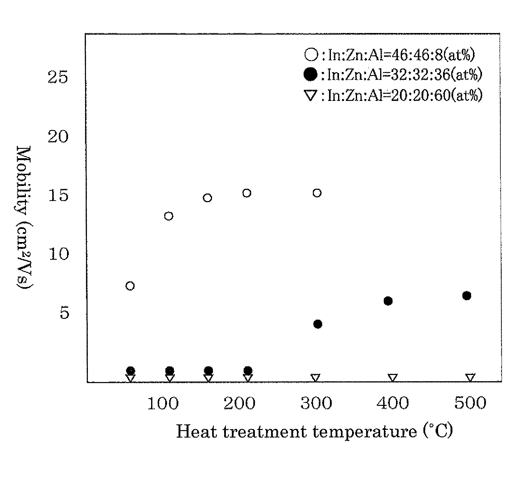
[0277]As the raw material, 5N (purity: 99.999%) indium oxide powder (INO04PB, manufactured by Kojundo Chemical Laboratory Co., Ltd.), 5N zinc oxide powder (ZNO04PB, manufactured by Kojundo Chemical Laboratory Co., Ltd.) and 5N aluminum oxide powder (manufactured by Kojundo Chemical Laboratory Co., Ltd.) were mixed such that the atomic ratio [In / (In+Zn+Al)] became 0.48, the atomic ratio [Zn / (In+Zn+Al)] became 0.50 and the atomic ratio [Al / (In+Zn+Al)] became 0.02. The mixture was supplied to a wet type ball mill and pulverized and mixed for 72 hours to obtain raw material fine powder.

[0278]The resulting raw material fine powder was granulated, and press-molded into a size of 10 cm in diameter and 5 mm in thickness. The molded product was put in a firing furnace, and fired at 1500° C. for 12 hours, whereby a sintered body (target) was obtained.

[0279]The target was pulverized and analyzed by ICP, and it was found that impurities such as Sn (tin), Ge (germanium), Si (silicon), Ti...


PUM

PropertyMeasurementUnit
treatment temperatureaaaaaaaaaa
temperatureaaaaaaaaaa
purityaaaaaaaaaa

Abstract

A field effect transistor including a semiconductor layer including a composite oxide which contains In, Zn, and one or more elements X selected from the group consisting of Zr, Hf, Ge, Si, Ti, Mn, W, Mo, V, Cu, Ni, Co, Fe, Cr, Nb, Al, B, Sc, Y and lanthanoids in the following atomic ratios (1) to (3):In / (In+Zn)=0.2 to 0.8  (1)In / (In+X)=0.29 to 0.99  (2)Zn / (X+Zn)=0.29 to 0.99  (3).

Description

[0001]This application is a 371 of PCT / JP2008 / 073252, filed Dec. 19, 2008.TECHNICAL FIELD[0002]The invention relates to a field effect transistor using an oxide semiconductor film as a channel layer and a method for producing the same.[0003]A field effect transistor such as a thin film transistor (TFT) is widely used as a unit electronic element of a semiconductor memory integrated circuit, a high-frequency signal amplification element, a liquid crystal driving element or the like. It is an electronic device which is most practically used recently.[0004]Of these, with a remarkable development of displays in recent years, a TFT is widely used as a switching element which serves to drive a display by applying a driving voltage to a display element in various displays such as liquid crystal displays (LCD), electroluminescence displays (EL) and field emission displays (FED).[0005]As the material for a semiconductor layer (channel layer) which is the primary element of a field effect tra...

Claims


Application Information

Patent Timeline
Patent Type & Authority Patents(United States)
IPC IPC(8): H01L29/786H01L29/221
CPCH01L29/7869C23C14/086H01L29/263H01L29/78693
Inventor YANO, KOKIKAWASHIMA, HIROKAZUINOUE, KAZUYOSHITOMAI, SHIGEKAZUKASAMI, MASASHI
Owner IDEMITSU KOSAN CO LTD
Why Eureka
Try Eureka