Continuous or discrete metallization layer on a ceramic substrate

a technology of ceramic substrate and metallization layer, which is applied in the direction of metallic material coating process, solid-state device, chemical vapor deposition coating, etc., can solve the problems of high cost of both techniques, limited thin film circuit, and conductors with only 30 to 60 percent of pure metal conductivity, etc., to achieve high thermal and electrical conductivity and high adhesion strength of metallization

Inactive Publication Date: 2013-12-17
SELEZNEV MAXIM
View PDF9 Cites 2 Cited by
  • Summary
  • Abstract
  • Description
  • Claims
  • Application Information

AI Technical Summary

Benefits of technology

[0013]Surface metallization technology for ceramic substrates is disclosed herein. It makes use of a known phenomenon that many metal-metal oxide alloys in liquid state readily wet an oxide ceramic surface and strongly bond to it upon solidification. To achieve high adhesion strength of a metallization to ceramic, a discrete metallization layer consisting of metal droplets bonded to ceramic surface using metal-metal oxide bonding process is produced first. Next, a continuous metal layer is deposited on top of the discrete layer and bonded to it using a sintering process. As a result a strongly adhering, glass-free metallization layer directly bonded to ceramic surface is produced. In particular, the process can be successfully used to metallize aluminum nitride ceramic with high thermal and electrical conductivity copper metal.

Problems solved by technology

Both techniques are costly.
However, due to their high costs, thin film circuits have been limited to specialized applications such as high frequency and military applications where a high pattern resolution is vital.
A disadvantage in using thick film printed circuits is that the conductors have only a 30 to 60 percent of the conductivity of the pure metal.
Another disadvantage of thick film technology is that it cannot be applied to aluminum nitride substrates because of a close to zero adhesion of glass to aluminum nitride.
However, this method suffers from many technological problems, most serious of which is entrapment of gases that cause blistering between the metal layer and the substrate leading to poor yields and high production costs.
Also, in order to produce a well-adhered copper foil with minimum blisters, the process parameters have to be controlled very closely, which is hard to do under commercial operating conditions
Although the process of Elmore provides good surface coverage it reached only limited acceptance for commercial production because of low adhesion, primarily because the alkaline surface treatment weakens the ceramic surface structure.
However, the method of this patent was able to achieve only 1.7 MPa bond strength.
This bond strength is too low for practical use.
Therefore, prior art processes suffer from high costs, or low electrical and thermal performance of metallization layer, or high rejection rate due to blister-prone substrates, or unacceptably low metallization bond strength and are in general unsatisfactory for commercial product purposes.
Previous attempts to reproducibly manufacture metallized ceramic substrates, particularly aluminum nitride, only experienced limited success.

Method used


Image

  • Continuous or discrete metallization layer on a ceramic substrate
  • Continuous or discrete metallization layer on a ceramic substrate
  • Continuous or discrete metallization layer on a ceramic substrate

Examples


example 1

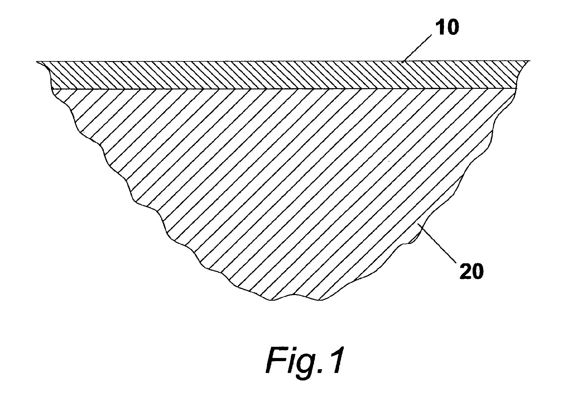
[0048]Approximately 50 by 50 by 0.65 mm AlN substrate available commercially, with specified thermal conductivity of 170 W / mK was placed in a quartz tube furnace and heated up to 1150 degrees Celsius in high purity oxygen atmosphere at a heating rate of 600 degrees Celsius per hour. It was held at that temperature for 24 hours in order to form an alumina oxide layer on the substrate surface and then slowly cooled down to room temperature at a natural cool down rate of the furnace.

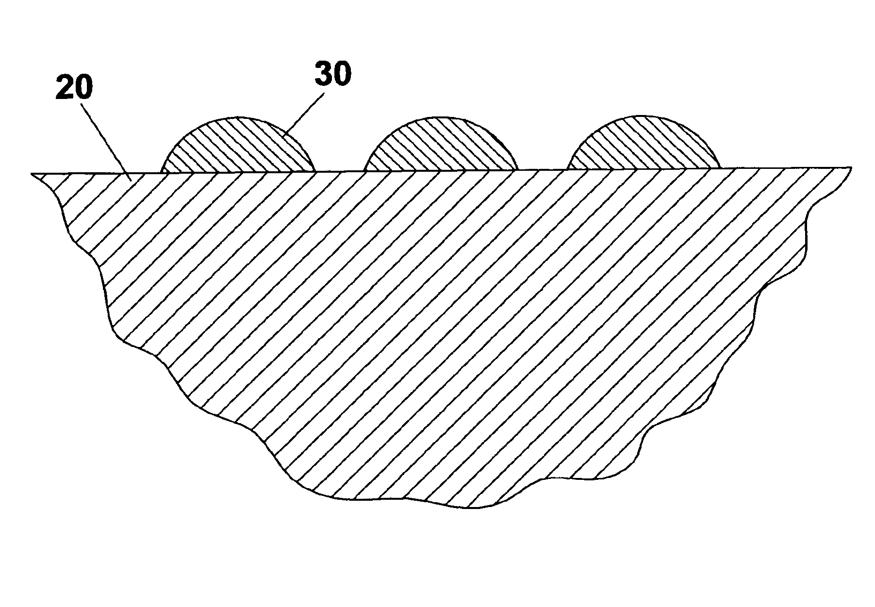
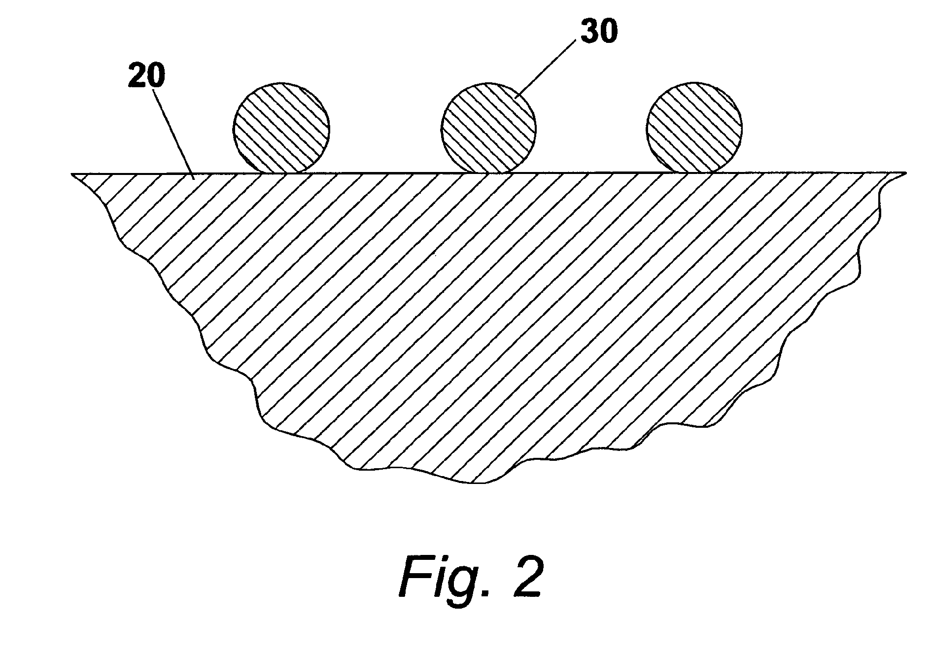
[0049]After oxidizing heat treatment a 1 micrometer thick copper coating was deposited on one of the substrate faces using thermal evaporation technique. Next the substrate was placed into a quartz tube furnace and heated up to 1090 degrees C. in high purity nitrogen atmosphere at a heating rate of 600 degrees C. per hour. It was held at that temperature for 15 minutes, so that the copper layer on ceramic surface had time to melt and break down into liquid copper droplets shaped as a dome with a contact ang...

example 2

[0050]Approximately 50 by 50 by 0.65 mm AlN substrate available commercially, with specified thermal conductivity of 170 W / mK was placed in a quartz tube furnace and heated up to 1150 degrees Celsius in high purity oxygen atmosphere at a heating rate of 600 degrees Celsius per hour. It was held at that temperature for 24 hours in order to form an alumina oxide layer on the substrate surface and then slowly cooled down to room temperature at a natural cool down rate of the furnace.

[0051]After oxidizing heat treatment one face of the substrate was subjected to kinetic spray deposition of copper layer. Deposition was carried out using 20 microns average particle size 99.9% pure copper powder and air jet at 200 degrees C. temperature. Deposition resulted in formation of approximately 1-3 micrometers thick copper metallization layer.

[0052]Next the substrate was placed into a quartz tube furnace and heated up to 1090 degrees C. in high purity nitrogen atmosphere at a heating rate of 600 d...


PUM

PropertyMeasurementUnit
contact angleaaaaaaaaaa
temperatureaaaaaaaaaa
thicknessaaaaaaaaaa

Abstract

Surface metallization technology for ceramic substrates is disclosed herein. It makes use of a known phenomenon that many metal—metal oxide alloys in liquid state readily wet an oxide ceramic surface and strongly bond to it upon solidification. To achieve high adhesion strength of a metallization to ceramic, a discrete metallization layer consisting of metal droplets bonded to ceramic surface using metal—metal oxide bonding process is produced first. Next, a continuous metal layer is deposited on top of the discrete layer and bonded to it using a sintering process. As a result a strongly adhering, glass-free metallization layer directly bonded to ceramic surface is produced. In particular, the process can be successfully used to metalize aluminum nitride ceramic with high thermal and electrical conductivity copper metal.

Description

CROSS REFERENCE TO RELATED APPLICATIONS[0001]This application is for entry into the U.S. National Phase under §371 for International Application No. PCT / US2009 / 002724 having an international filing date of Apr. 30, 2009, and from which priority is claimed under all applicable sections of Title 35 of the United States Code including, but not limited to, Sections 120, 363 and 365(c), and which in turn claims priority under 35 USC 119 to U.S. Patent Application No. 61 / 126,158 filed on May 1, 2008.FEDERALLY SPONSORED RESEARCH[0002]Not ApplicableSEQUENCE LISTING OR PROGRAM[0003]Not ApplicableFIELD OF THE INVENTION[0004]This invention relates to processing method to manufacture metallized ceramic substrates for electronic packaging applications.BACKGROUND OF THE INVENTION[0005]Metallized ceramic substrates find wide usage for electronic packaging applications, exemplary of which are high density DC / DC converters, power amplifiers, RF circuitry and high current switches. These metallized c...

Claims


Application Information

Patent Timeline
Patent Type & Authority Patents(United States)
IPC IPC(8): C23C14/14F27B14/00H05B6/02B05B3/00B05D5/06C23C16/00C21D9/00C21D5/00
CPCC04B37/026C04B41/009C04B41/52C04B41/90H01L21/4846H01L23/3735C04B41/4519C04B41/4556C04B41/5031C04B41/0072C04B41/4529C04B41/4572C04B41/5127C04B41/4539C04B35/581C04B2111/00844C04B2235/6565C04B2235/96C04B2237/124C04B2237/366C04B2237/407C04B2237/54C04B2237/706H01L2924/09701H01L2924/0002H01L2924/00
Inventor SELEZNEV, MAXIM
Owner SELEZNEV MAXIM
Why Eureka
Try Eureka