Optical barriers, waveguides, and methods for fabricating barriers and waveguides for use in harsh environments

a technology of optical barriers and waveguides, applied in the field of fiberoptic sensing, can solve the problems of significant deformation of sensor performance, incomplete failure of thermocouples, and unreliable temperature sensing

Active Publication Date: 2014-10-07
THE RES FOUND OF STATE UNIV OF NEW YORK
View PDF14 Cites 5 Cited by
  • Summary
  • Abstract
  • Description
  • Claims
  • Application Information

AI Technical Summary

Problems solved by technology

As known in the art, the problem associated with thermocouple-based sensing probes is that the sensor performance degrades significantly with time.
These disadvantages of thermocouple-based sensing often result in unreliable temperature sensing or even a complete failure of the thermocouples.
Regarding the thermal radiation based sensing, despite the advantage of being a non-contact method for temperature measurements, thermal radiation based sensing devices are typically impractical, or even impossible, for large-scale deployment in multi-point sensing applications.
Accordingly, the stringent requirements for high temperature sensing under harsh conditions have made the conventional thermoelectric thermal radiation sensing methods inadequate for harsh conditions.
Though silica based fibers can provide effecting sensors, silica-based fibers are not applicable for sensing at ambient temperatures greater than 800 degrees C., because, as noted by Fernando, et al.
Since chemical reactions between fiber materials and their surroundings can substantially change fiber material properties, resulting in severe degradation in sensor performance, and even the complete failure of sensors due to chemical corrosion.
Though, as shown in Table 1, sapphire fibers have marked differences in characteristics that suggest sapphire is preferable to silica for harsh environments, the major issue limiting the use of sapphire-based fiber sensors in an industrial setting is the lack of reliable claddings for sapphire fibers, particularly at temperatures above 1000 degrees C.
In addition, small size sapphire fibers (that is, having an outside diameter less than 10 micrometers [μm]) are currently unavailable in the field, and thus single-mode optical propagation within sapphire fibers is essentially impossible, which is another drawback for sapphire-based fiber-optics sensing.
Although the refractive index of air is less than that of fiber materials, air cannot serve as an effective cladding for sapphire fibers.
These characteristics of sapphire fibers can cause difficulties for the fabrication and operation of sapphire fiber sensors.
Moreover, a further disadvantage of sapphire-fiber-based sensing is that the intensity of optical signals in sapphire fibers can be significantly decreased as a result of strong light scattering at the fiber-air interface, if the fibers are not properly clad.
This is particularly severe for sensing applications in harsh environments where constantly varied surrounding atmospheres, deposited dust, and defects (for example, scratches and / or cracks) can develop on the fiber surface, among other places, that can result in unsatisfactory optical signal losses.
Accordingly, the use of sapphire-based optical sensors can be impractical, or even substantially impossible, for delivering and detecting optical signals when a large fiber length (that is, greater than 0.5 m) is needed, as in the case of multi-point sensing for oversized facilities, such as, power plants and gasifiers.
However, the presence of cladding can also affect the number of propagating modes allowable within fibers.
Unlike silica-based fibers, core-clad structures for single crystal sapphire fibers are unattainable during their growth.
However, none of these efforts has yielded satisfactory performance for sapphire fiber cladding in harsh environments, particularly at temperatures around and above 1000 degrees C.
For ambient temperatures above 1000 degrees C., even a small difference in such thermal characteristics between sapphire and the cladding material can result in mechanical failures (for example, cracking and / or delamination of the cladding from the fiber surface) of claddings due to stress buildup.
It is well known in the art that, with the present state of the art, it is very difficult (if not impossible) to obtain a cladding material that satisfies all these stringent requirements that can be used effectively for sapphire fiber cladding, for example, for harsh environment sensing applications.
Consequently, the inventors have found that there has been no viable technology available in the art that would allows sapphire fibers to be properly clad for use under harsh-environment conditions, for example, involving high temperatures (for example, greater than 1000 degrees C.) and resistance to high chemical corrosion and / or erosion.
As known in the art, the electronic polarizability (α) depends on the chemical bonding of the material, and a dramatic reduction in the electronic polarizability is typically difficult to achieve without significant change of constituting chemical species in the material matrix.
During this impingement, various ion-solid interactions take place as the energetic ions traverse the material, and typically lead to modifications in material properties.
These nuclear collisions displace the constituent atoms from their original locations, leaving a high density of defects (for example, voids, vacancies, and / or interstitials) in the material.
However, the present inventors have found that this prior art has been limited to room temperature or relatively low processing temperatures conditions for the fabrication and operation of ion implantation produced waveguides, specifically to processing temperatures less than 200 degrees C. Accordingly, the prior art teachings, waveguides, and barriers are not applicable to conditions for higher temperatures, for example, temperatures greater than 200 degrees C., that is, those temperatures that characterize the harsh environments typically encountered in certain industrial processes, as discussed above.

Method used


Image

  • Optical barriers, waveguides, and methods for fabricating barriers and waveguides for use in harsh environments
  • Optical barriers, waveguides, and methods for fabricating barriers and waveguides for use in harsh environments
  • Optical barriers, waveguides, and methods for fabricating barriers and waveguides for use in harsh environments

Examples


Embodiment Construction

[0070]The present invention, in its several embodiments and many aspects, is based upon the use of charged particle implantation, for example, hydrogen ion implantation, combined with high temperature annealing to induce structural modifications (for example, local volume / density, stoichiometry and chemical bonding) in produce barriers to electromagnetic radiation in substrates, for example, thermally, mechanically and chemically stable barriers to electromagnetic radiation.

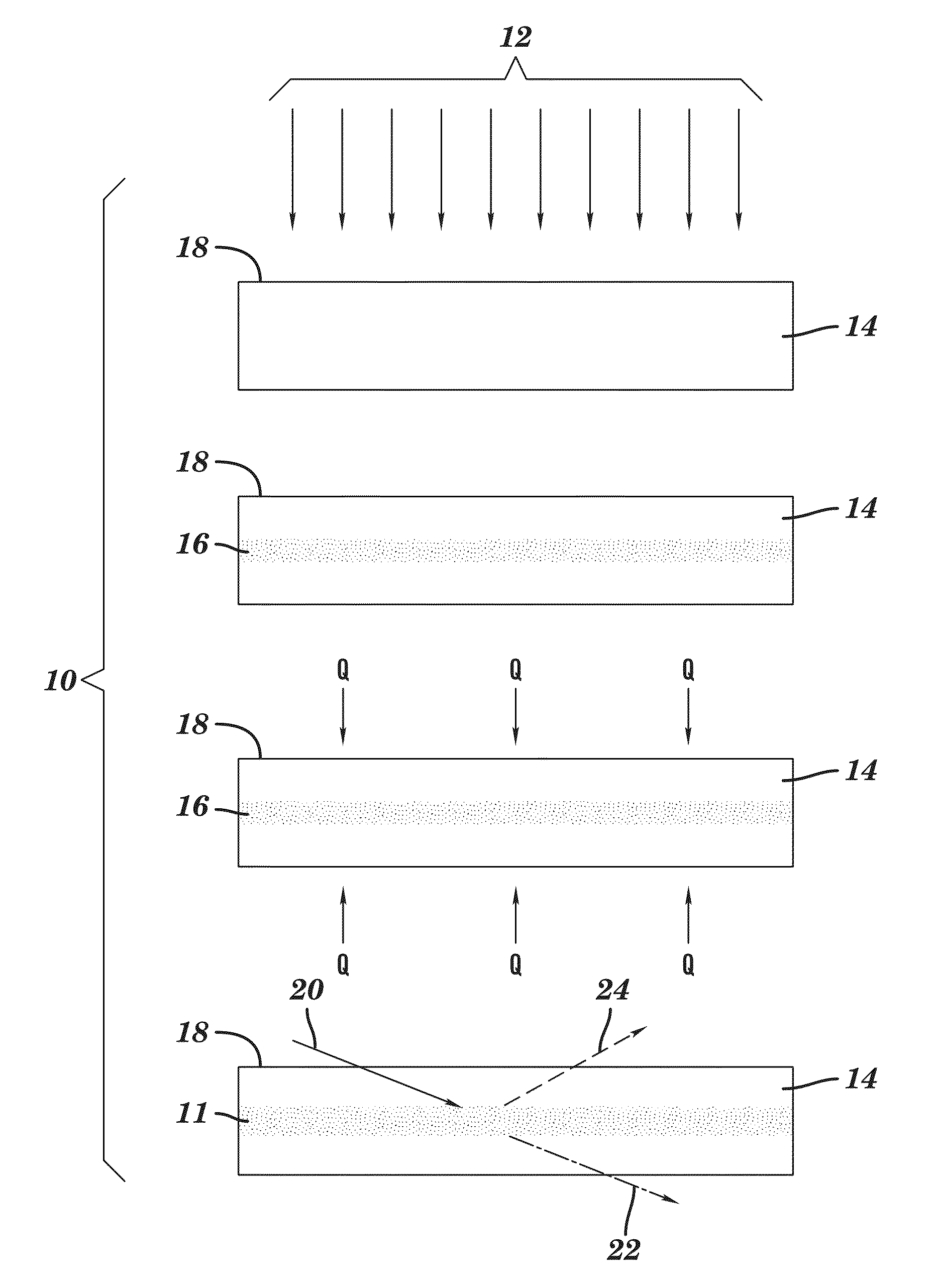
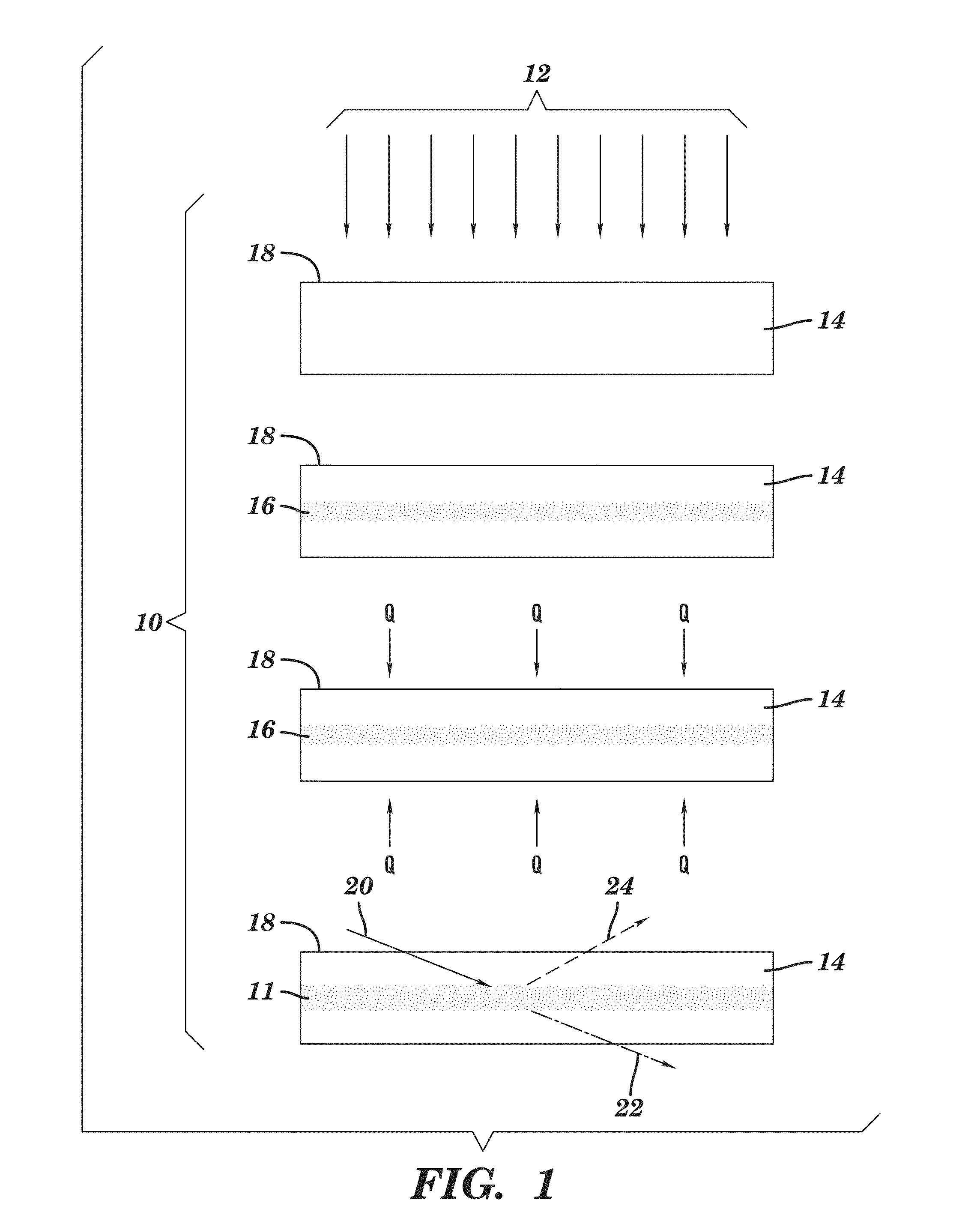
[0071]FIG. 1 provides a schematic illustration of one aspect of the present invention, in particular, a method 10 of fabricating an electromagnetic radiation barrier 11, for example, for confining electromagnetic radiation through a waveguide. As shown in FIG. 1, the method 10 includes or comprises first directing a stream of charged particles 12 into a substrate 14. The charged particles 12 may be electrons, protons, and / or ions, for example, in one aspect, charged particles 12 may be hydrogen ions, that is, sub...


PUM

PropertyMeasurementUnit
diameteraaaaaaaaaa
lengthaaaaaaaaaa
energyaaaaaaaaaa

Abstract

Electromagnetic radiation barriers and waveguides, including barriers and waveguides for light, are disclosed. The barriers and waveguides are fabricated by directing charged particles, for example, ions, into crystalline substrates, for example, single-crystal sapphire substrates, to modify the crystal structure and produce a region of varying refractive index. These substrates are then heated to temperatures greater than 200 degrees C. to stabilize the modified crystal structure and provide the barrier to electromagnetic radiation. Since the treatment stabilizes the crystal structure at elevated temperature, for example, above 500 degrees C. or above 1000 degrees C., the barriers and waveguides disclosed are uniquely adapted for use in detecting conditions in harsh environments, for example, at greater than 200 degrees C. Sensors, systems for using sensors, and methods for fabricating barriers and waveguides are also disclosed.

Description

FEDERALLY FUNDED RESEARCH[0001]The invention described herein was made with U.S. Government support under Federal Grant Number CMMI-0926141 awarded by the National Science Foundation (NSF). The U.S. Government has certain rights to this invention.BACKGROUND OF THE INVENTION[0002]1. Technical Field[0003]The invention disclosed herein relates to optical barriers and waveguides and the fabrication and use of optical barriers and waveguides for transmitting electromagnetic radiation. Specifically, the invention relates to the fiber-optic sensing under harsh conditions and the fabrication of barriers and waveguides by ion implantation and annealing at high temperatures.[0004]2. Description of Related Art[0005]Sensing and / or monitoring of physical parameters (for example, temperature, pressure, etc.) in harsh environments is critically demanded by many industrial applications, including combustion related applications, such as, in power engines, in power plants, in coal gasification, and ...

Claims


Application Information

Patent Timeline
Patent Type & Authority Patents(United States)
IPC IPC(8): C23C14/48
CPCG02B6/03666C23C14/48C30B29/20G21F1/00C30B33/04
Inventor HUANG, MENGBINGSPRATT, WILLIAM T.
Owner THE RES FOUND OF STATE UNIV OF NEW YORK
Why Eureka
Try Eureka