This response to sub-optimal bone loading can lead to loss of proximal support, implant
subsidence, potential
bone fracture, possible fatigue fracture of the implant, and, most importantly, reduction of
bone stock that jeopardizes the outcome of any future revision
surgery.
Despite widespread awareness of these factors, the problem of implant stiffness has not been completely solved.
Past attempts to incorporate design features that reduce
flexural rigidity have yielded inconsistent results or failures due to
biomaterial incompatibilities and practical manufacturing complications.
While research efforts have focused on the clinical problems associated with
total hip arthroplasty (THA), similar problems exist with other orthopaedic implants.
However, problems associated with implant loosening along with proximal and distal migration tempered early enthusiasm for these designs.
Over the intervening years, painful loosening of the implant became more common.
One
disadvantage of this increase in
implant size is a larger mismatch in stiffness between the implant and the adjacent bone than would be typical of stems that rely on
cement for fixation.
Filling this hollow tube with a
metal prosthesis stiffens the tube and accordingly reduces its ability to bend in response to the applied load.
There is no standard testing protocol, nor a consistent definition of this phenomenon.
The mechanical parameters that regulate
periprosthetic bone loss are difficult to quantify.
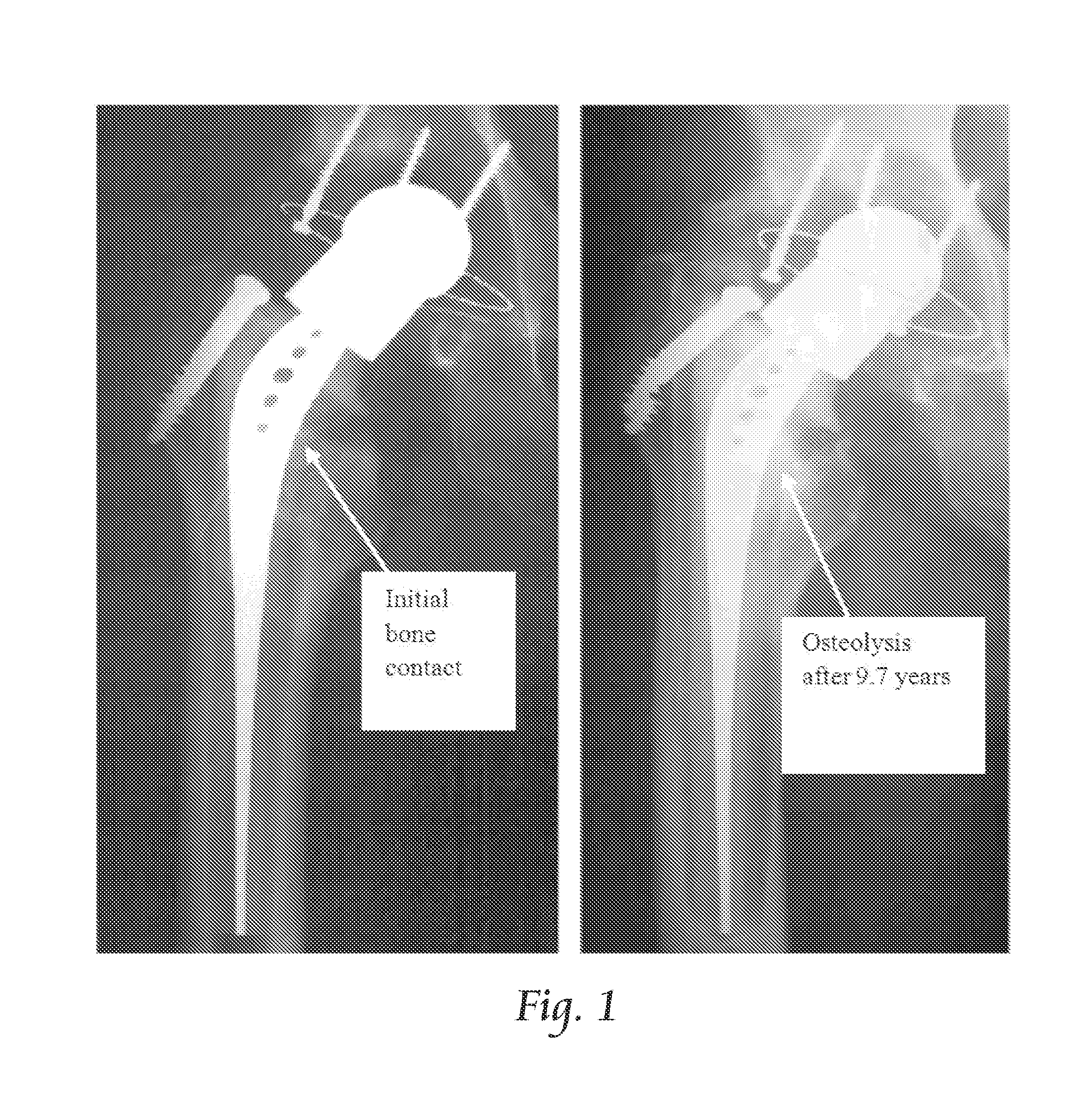
A concern with THA prostheses is the possibility that resorptive
bone remodeling will, in the long term, lead to loss of proximal implant support, implant subsistence and implant or bony fracture.
Studies by Lewis et al. on the influence of prosthetic stem rigidity suggest that the loss of proximal support due to
bone resorption, with firm fixation distally, may also be a major cause of fatigue failure of femoral stems.
Thus, whether the clinical concern is
initial fixation, loosening,
subsidence, or stem fracture, the bone loss due to
stress shielding impairs the construction as a whole and can lead to inadequate support for a revision implant in the future.
Kiratli et al. evaluated post-operative bone loss using DEXA and concluded that
bone remodeling does not stabilize in two years.
Other assessments of bone loss over time are often inconclusive as early clinical studies of
bone resorption relied on radiographic measurements that predated DEXA technology.
Despite these
data accuracy concerns, the study by Huiskes et al. on
stress shielding and
bone resorption notes that even if the
bone remodeling process does stop after a few years, a loss of proximal
bone mass on the order of 50% “provides little confidence for the time when these patients get older and become prone to falls and other accidents as .
. . the remaining bone may not be adequate to withstand the
impact forces”.
However, research indicates that the loss of proximal support increases the risk of fatigue fracture of the stem and jeopardizes any future revision that would require extraction of an otherwise well-fixed stem.
Surgery of this type is a technically challenging procedure that may not leave adequate bone for satisfactory support of a revision implant.
Significant
thigh pain after implantation of a cementless
prosthesis occurs in as many as 20% of
arthroplasty patients, a problematic outcome as one of the clinical indications for performing THA in the first place is
joint pain.
Although the
etiology of
thigh pain is unclear, research suggests that it is attributable to excessive stem stiffness and the resulting modulus mismatch between implant and
host bone.
Early attempts to incorporate design features that reduce the flexural rigidity of the implant and minimize bone
resorption due to
stress shielding have led to inconsistent results and, in some cases, catastrophic failures.
An early evaluation by Morscher et al. of the RM Isoelastic (RMI) implant focused on testing done to assure
biocompatibility but offers little quantitative data regarding the stiffness of the implant.
However, earlier assessments which lacked the accuracy of DEXA technology concluded that “while early results are encouraging, this prosthesis needs a longer follow-up evaluation to prove its effectiveness”.
In a 7-9 year follow-up study, Niinimaki et al. acknowledged that while early results were encouraging, the RMI stem shows a
high rate of loosening and the results are “worse than those reported for other uncemented stems”.
In another evaluation of the RMI prosthesis, Au noted that the perceived
advantage of isoelasticity “is hard to justify in clinical practice”.
The clinical review of this prosthesis by Jakim et al. concluded that the concept of isoelasticity has failed to fulfill original clinical expectations and that “it seems unlikely that an ideal mimic can be fashioned from
plastic materials”.
The hollow Cenos (Artos Medizinische Produkte GmbH, Berlin, Germany) stem relies on extra flexibility to reduce stress shielding with “very satisfying” but unquantified results reported by Schmidt et al. after 1 year of clinical experience.
Effects of these modifications were inconclusive and influenced by other design or manufacturing issues.
A subsequent
clinical evaluation by Jacobsson et al. noted that the flexible stem of the Butel
femoral component produces high shear forces in the proximal interface which has led to loosening, overload on the prosthesis and fatigue fracture.
While a 3-6 year evaluation disclosed acceptable overall results and a significant reduction in
thigh pain, the effect of the slotted distal stem design does not address proximal implant stiffness, the zone in which the greatest mismatch in rigidity occurs.
Clinical trials by Nistor et al. of the LMPCH
titanium stem (Biomet, Inc., Warsaw, Ind.) layered with
solid and porous
polyethylene were generally not successful due to implant
subsidence.
The
clinical study of the Epoch stem by Glassman et al., showed stable
initial fixation and minimal micromotion but the study was “too short to determine the long-term outcome of the procedure” relative to adaptive bone remodeling.
In a 2000 paper by Simões et al., the authors note that the development of a controlled-stiffness implant is limited by currently available materials and the fabrication process involved.
“At present, for the hip prosthesis, this remains a theoretical solution since it is difficult to manufacture a device with a very highly differentiated modulus”.
Despite these perceived advantages, the clinical success of
carbon fiber composite femoral implants has been limited by problems with stem fracture and inadequate fixation at the
polymer-bone interface.
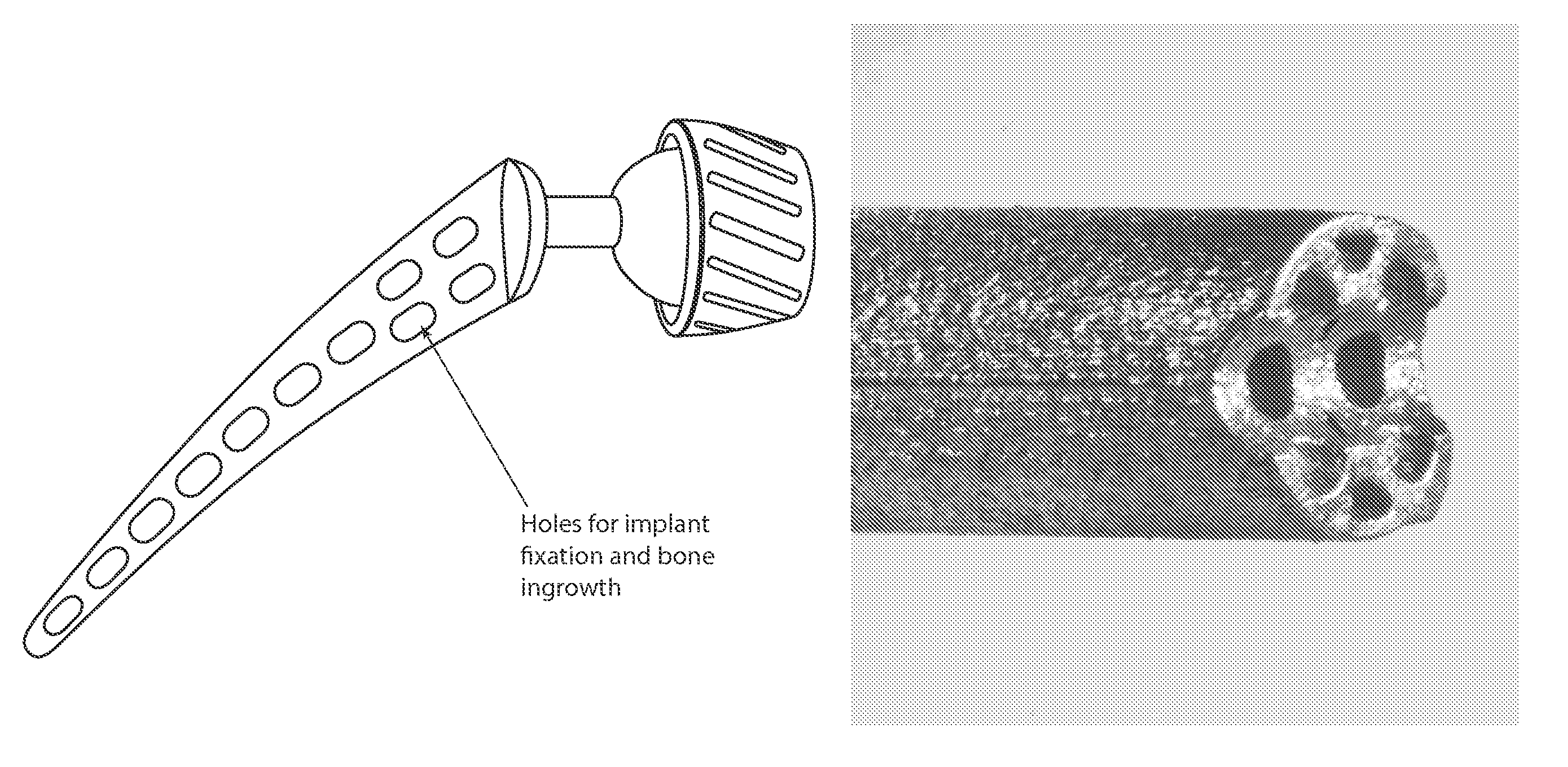
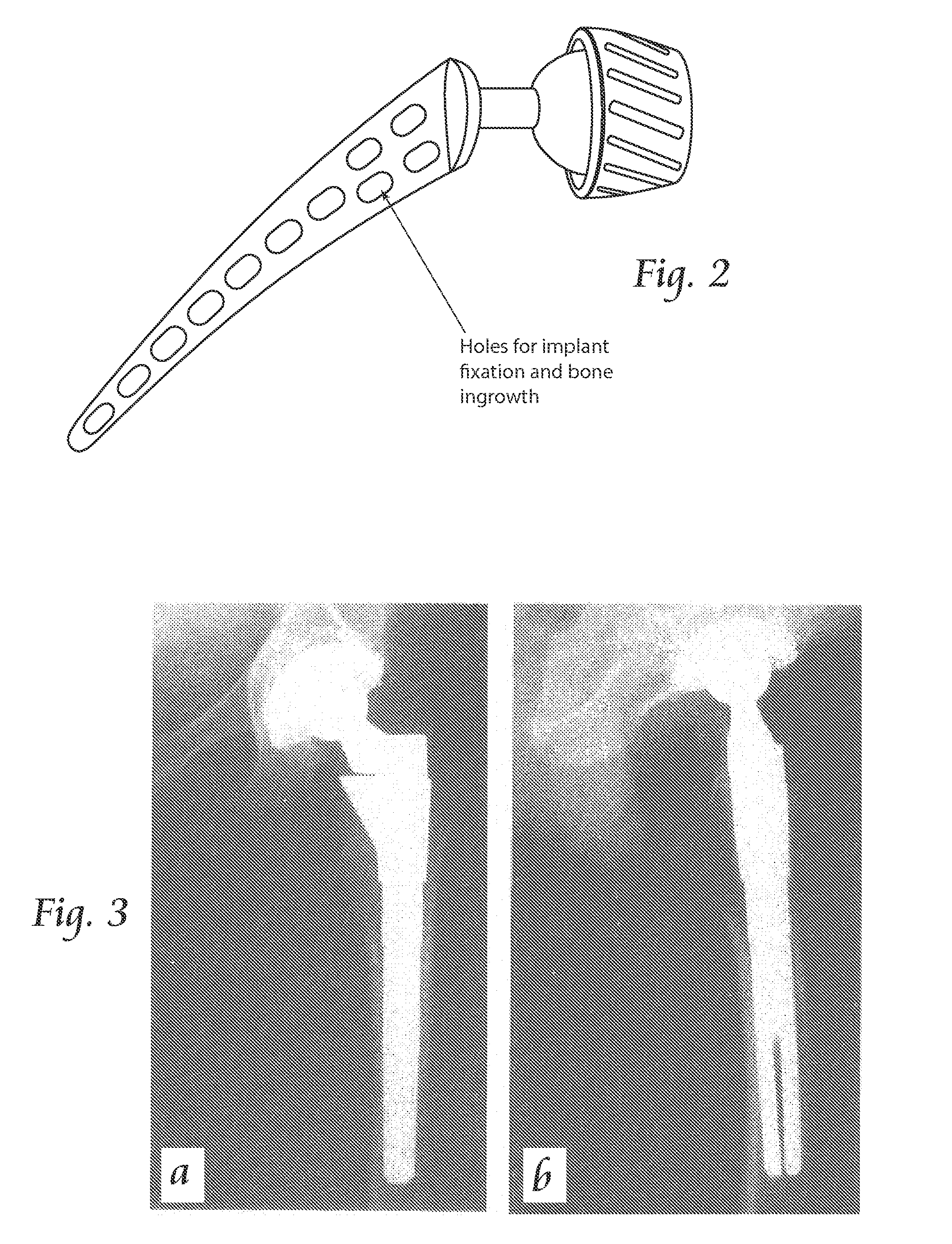
These composite implants lack the ability for
osseointegration as they cannot be fabricated with conventional porous coatings or other
bone ingrowth surfaces.
Although implant manufacturers have long promoted the use of
titanium alloy stems as a “less stiff” material, adequate consideration of the consequences of stem geometry has been lacking.
However, even with smaller stem sizes, the
proximal femur is still understressed by at least 10-fold with a Ti implant when compared to the stresses in the intact
femur.
While this predates recent concerns regarding micromotion at the bone-implant interface, some implant designs have incorporated structural design features which (either intentionally or as a result of unrelated requirements) have reduced the stiffness of the implant.
“Reducing the stem stiffness decreases the amount of stress shielding and hence the amount of bone loss.
However, this measure inevitably promotes higher proximal interface stresses and thereby increases the risk of proximal interface failure.
The success of prior efforts to implement this scheme has been limited by combination of
biomaterial incompatibilities, practical manufacturing complications and insufficient understanding of flexural rigidity as it is applied to orthopaedic implants.
Ryan et al. noted that while the use of
titanium (Ti) in implants reduces the extent of stress shielding as compared to that of
cobalt-
chromium (CoCr), the stiffness mismatch is still substantial.
The physical meaning of these relationships is often unclear as most
theoretical models are based on some idealized physical
microstructure (e.g., uniform cubic, cylindrical or spherical pores arranged in a cubic array), and the resulting correlations often cannot be extended to real materials and potential clinical applications.
While the literature abounds with references to different
porosity models and their appropriateness for a given set of conditions, the problem is that the
microstructure corresponding to a particular formula is not precisely known.
Thus, agreement or disagreement with data can neither confirm nor reject a particular model.
However, despite the extensive body of research represented by existing
porosity-property relationships, most lack predictive ability.
Rice is critical of much of the prior work as “few investigators studying the dependence of elastic properties on
porosity present anything more than density, i.e., average porosity data” when pore shape
anisotropy can significantly alter these relationships and invalidate the results.
Boccaccini added that most experimental studies in the open literature dealing with porous materials do not supply accurate quantitative descriptions of the porosity structure and cannot be considered for rigorous
verification of theoretical approaches.
In a 1996 paper on
physical property-porosity models, Rice notes that the use of spherical particles or pores in the three basic close packings (cubic, orthorhombic and rhombohedral) has not been adequately evaluated and “
isotropy has apparently not been considered before” as the presumption is that the mechanical properties of porous structures are isotropic.

