Wafer fabrication monitoring/control system and method
a monitoring/control system and control system technology, applied in the direction of individual semiconductor device testing, semiconductor/solid-state device testing/measurement, instruments, etc., can solve the problems of increasing the collateral plasma induced damage, reducing the robustness of the osg, and reducing the electrical reliability
- Summary
- Abstract
- Description
- Claims
- Application Information
AI Technical Summary
Benefits of technology
Problems solved by technology
Method used
Image

Examples
example 1
Photolithography and Photoresist Characterization
[0092]To illustrate the effectiveness of MIR-IR of certain embodiments of the invention for the characterization of photoresist, an experiment was carried out using a thin (1202 is pressed against a waveguide substrate 1205; FIG. 12B shows a representation of a MIR-IR system method where the substrate having photoresist 1210 provides a waveguide in accordance with an embodiment of the invention; and FIG. 12C shows a comparison plot of the IR spectra obtained via the external ATR IR spectroscopy method and via the MIR-IR system method in accordance with an embodiment of the invention.
[0093]As shown in the comparison plot of FIG. 12C, MIR-IR is capable of detecting the thin photoresist coating on a Si wafer with greater intensity and superior spectral resolution than is possible with external ATR IR. In addition, as illustrated by the sensitivity shown in the MIR-IR plot in FIG. 12C, MIR-IR is well suited for monitoring time-dependent c...
example 2
Plasma Reactive Ion Etching (RIE) Processes
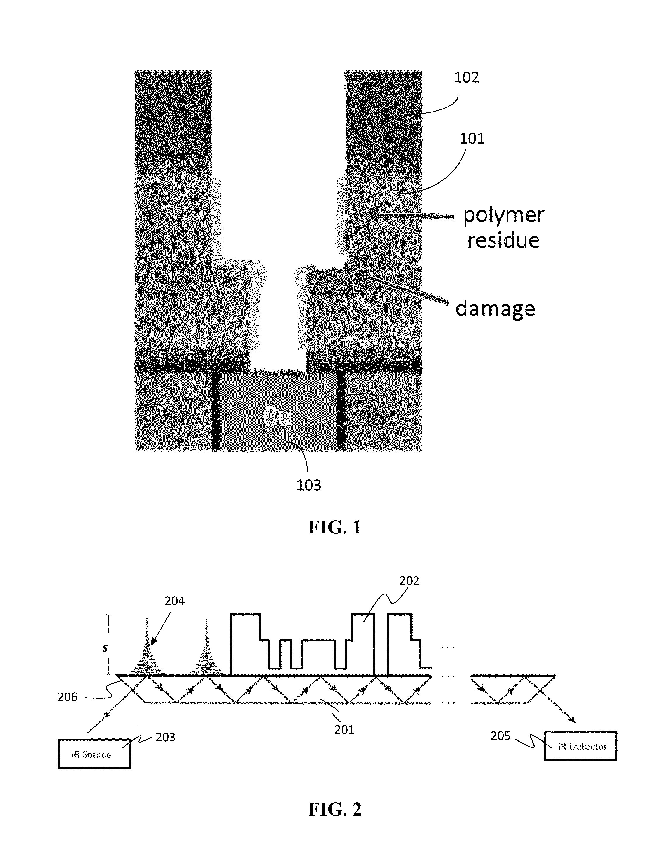
[0095]To illustrate the effectiveness of an MIR-IR system and method of certain embodiments of the invention to characterizing RIE processes, experiments were conducted for removal of organic polymers (photoresist) deposited on 190 nm carbon doped oxide (CDO) thin film (an ILD material) on a silicon wafer.
[0096]FIG. 13 indicates potential unique IR peaks from post-etch residues that can be used directly for quantification. With proper base-line determination, the absorbance (peak height) can provide the relative quantification of post-etch residues in the patterned ILD film stack.
[0097]As illustrated by the spectra plot of FIG. 13, the integrated IR peak absorbance enables a reliable basis for post-etch residues quantification. The results can be correlated to the H / F / O atomic ratio in etch gases, type of low-k / ULK ILD chemistry, and energetic characteristics of plasma. Concurrently, the IR absorbance of methyl termination (—CH3, 2970 cm−1)...
example 3
Improvements to MIR-IR with Added Isotope Effect
[0104]The IR absorption peak locations (e.g., wave number, frequency, absorbance can be shifted by using different isotopes (such as 13C and 18O) when performing plasma etching. The use of the isotopes enables additional improvements to characterization in certain embodiments employing the subject MIR-IR techniques. The IR absorption peak location shifts systematically according to the following equation for the stretching frequency (in reciprocal centimeters).
v=1 / 2πc√{square root over (k / μ)},
where v gives the stretching frequency / wavenumber of absorbance, k is the spring constant for the chemical bond, c is the speed of light, and μ is the reduced mass of the A-B system.
[0105]The reduced mass of the A-B system can be given by:
μ=mAmB / mA+mB,
where mi is the mass of atom i.
[0106]For example, replacing plasma etching gases (e.g., CF4, CH2F2, CO) with 13C enrichment, can shift the IR peak location to aid in identification and quantification...
PUM
 Abstract
Description
Claims
Application Information