Bionic artificial semi- joint body and manufacturing technique thereof

A manufacturing process and joint technology, applied in the field of bionic artificial semi-joint body and its manufacturing process, can solve the problems of joint prosthesis interface separation, difficult long-term fixation of joint prosthesis, inability to ensure the long-term integration of bone layer and bone tissue, etc. To achieve the effect of tight bonding, enhancing mobility and reducing friction damage

Inactive Publication Date: 2008-01-23
XI AN JIAOTONG UNIV
View PDF0 Cites 18 Cited by
  • Summary
  • Abstract
  • Description
  • Claims
  • Application Information

AI Technical Summary

Problems solved by technology

However, there are problems in the artificial joint body obtained by this method: on the one hand, because there is no pore structure dedicated to cell reproduction and blood circulation in the bone layer, it cannot ensure the good growth of the bone layer and bone tissue, and it is difficult to The position of the joint prosthesis is fixed for

Method used


Image

  • Bionic artificial semi- joint body and manufacturing technique thereof
  • Bionic artificial semi- joint body and manufacturing technique thereof

Examples


Embodiment 1

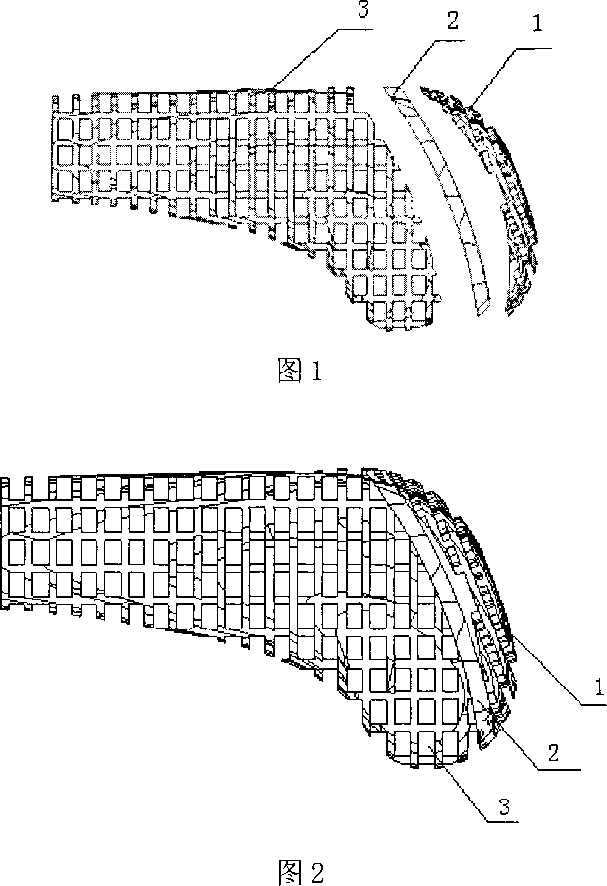
[0016] Example 1, referring to Figures 1, 2, 3, and 4, the preparation process of the present invention is as follows: first, according to the patient’s condition, the contour of the bionic artificial half joint is constructed by reverse engineering, and the three-dimensional design software is used to form the bionic artificial half joint. According to the interface shape and thickness data of the cartilage and bone layer of the half joint, the bone layer is divided into three parts: the upper layer 1, the middle layer 2 and the lower layer 3. The interior is designed according to the function of each layer Negative structure of the pipe column, that is, the upper layer 1 is a squirrel-cage column structure, the pipe column section is a uniform and regular structure, the middle layer 2 is a cavity structure, and the lower layer 3 has an orthogonal structure or other bionic pipe column structures that intersect each other perpendicularly. , And finally merge each layer model with ...

Embodiment 2

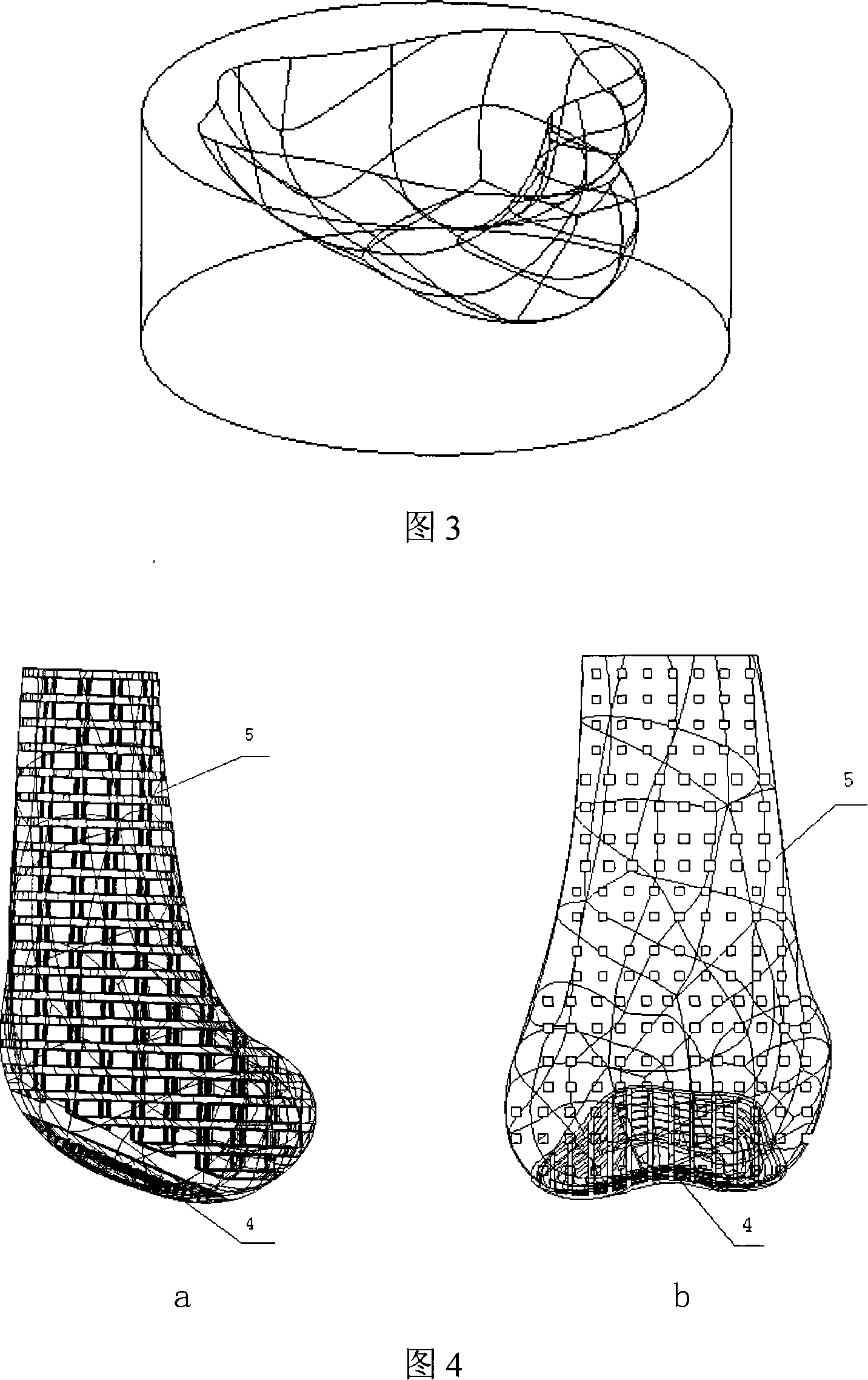
[0017]Example 2. In this implementation, hydroxyapatite (HAP), deionized water, acrylamide, sodium polyacrylate and N,N-dimethylene bisacrylamide, ammonium polyacrylate and N,N-diacetone Acrylamide is mixed uniformly according to the mass ratio of 115:80:6:1:1.3, put in a vacuum machine to remove bubbles, and adjusted with concentrated ammonia water to make the mixture PH=9 to obtain a slurry, and then add crosslinking agent to the slurry. 0.2 times the mass of sodium persulfate and N,N-dimethylcyclohexylamine form HAP ceramic slurry; fill the HAP ceramic slurry into the negative resin mold of the prosthesis structure, and place it in a vacuum high-temperature furnace from room temperature to The temperature rise rate of 100°C / hour is raised to 900°C for 1.8 hours to be cured, and then cooled to room temperature with the furnace; the other steps are the same as in Example 1, so that the bone layer material is ceramic part 4, and the cartilage layer elastomer material is polyuretha...

Embodiment 3

[0018] Example 3. In this example, aluminum oxide, deionized water, methyl-acyloxyethyl trimethyl ammonium chloride, sodium polyacrylate and dibenzylidene acetonyl acrylamide are combined according to 120:60:7:1.6 :1.5 mass ratio and mix uniformly, put it in a vacuum machine to remove bubbles, and adjust the pH of the mixture with concentrated ammonia water to obtain a slurry, and then add 0.2 times the mass of the crosslinking agent potassium persulfate and 0.5 times to the slurry. N,N,N′,N″,N″-pentamethyldiethylenetriamine is used to form alumina ceramic slurry; the alumina ceramic slurry is filled into the negative resin mold of the prosthesis structure and placed in a vacuum high-temperature furnace The temperature is raised from room temperature at a rate of 100°C / hour to 800°C for 2 hours to be solidified, and then cooled to room temperature with the furnace; the other steps are the same as in Example 1, so that the bone layer material is ceramic part 4, cartilage layer elas...


PUM

PropertyMeasurementUnit
Wavelengthaaaaaaaaaa
Diameteraaaaaaaaaa

Abstract

A simulation manual semi-joint body and fabrication technics are provided, which forms a shell model through reverse engineering and 3D design software and the divides the bone layer into three parts, namely upper, middle and lower layer; then designing the internal pipe column negative structure according to the funvtions of each layer and finally combining the model of each layer and the shell model to form the negetive model. The invention shapes the false body model by adopting the speedy shaping and exact photocureable forming machine, fills the ceramics slurry into the false body model and solidifies it in vacuum high temperature stove and then places the solidified ceramics body in polyurethane solution module; then pumping the vacuum, placing the module still and then taking out the ceramics after the polyurethane fully solidified; shaping it, thus achieving the bone layer material serving as the ceramics part; the soft bone layer elastomer is made of manual semi-joint body of the polyurethane elastomer. The invention reduces the rubbing damage for side joints and strengthens the activity capacity of the joints when the soft bone layer contacting the side joints.

Description

Technical field [0001] The invention belongs to the field of manufacturing engineering, and particularly relates to a bionic artificial half joint body and its manufacturing process. [0002] The new manufacturing process, in particular, it distinguishes cartilage and bone functions according to the anatomical characteristics of the joint, and designs the three-dimensional porous structure of the cartilage layer and the bone layer inside the artificial half joint body; and composites the polyurethane elastomer and the bioceramic material to form it. A bionic artificial half-articular body that can accurately match the complex profile of the joint defect area is developed. Background technique [0003] Joint disease is a common disease and frequently-occurring disease. In severe cases, it can cause joint movement dysfunction and even disability. It is necessary to replace the patient's half joint or full joint by joint replacement. For patients with damage to only one joint, espec...

Claims


Application Information

Patent Timeline
IPC IPC(8): A61F2/30A61L27/00
CPCA61F2/3094A61F2002/30001
Inventor 连芩李涤尘李翔靳忠民
Owner XI AN JIAOTONG UNIV
Why Eureka
Try Eureka