Method for preparing heaters by chemical vapor infiltration and resin impregnation, carbonization and densification

A chemical vapor infiltration and resin impregnation technology, applied in the direction of heating element materials, can solve the problems of low strength of graphite bolts, low yield, layering defects in the thickness direction, etc., to improve thermal shock resistance and structural stability, improve The ability to resist delamination and improve the effect of anti-scouring ability

Active Publication Date: 2010-02-03
XIAN CHAOMA SCI TECH
View PDF0 Cites 14 Cited by
  • Summary
  • Abstract
  • Description
  • Claims
  • Application Information

AI Technical Summary

Problems solved by technology

The continuous operation time of the hydrogenation furnace is more than 2000 hours, so the service life of the heating element will seriously affect the continuous operation time of the hydrogenation furnace
[0003] Chinese patent ZL200610043185X, titled "Preparation method of carbon/carbon heater for monocrystalline silicon drawing furnace and polycrystalline silicon smelting furnace", discloses the use of needle-punched carbon cloth and non-weft cloth to make full carbon fiber three-way structure heating The prefabricated body of the heater, the matrix adopts the binary carbon matrix of pitch carbon and resin carbon, and is purified under the condition of 2000-2500 ℃ with chlorine gas and freon. Composed of carbon fibers, the matrix carbon has a pitch carbon component with good electrical conductivity, and the temperature exceeds 2000 ° C. The resistance value of the carbon/carbon heating element is only 0.016~0.020Ω, which is one less than the required value. order of magnitude; (2) when furfurone resin or phenolic resin is impreg

Method used


Image

  • Method for preparing heaters by chemical vapor infiltration and resin impregnation, carbonization and densification

Examples


Embodiment 1

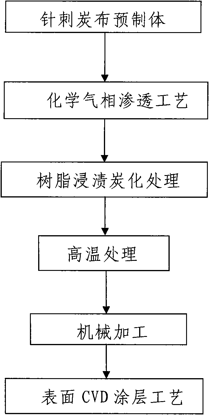
[0027] (1) Use 12K plain weave carbon cloth and short carbon fiber mesh alternately to form fibers in the plane direction, and adopt the needle punching process to introduce vertical fibers in the thickness direction to make a three-way structure heating element preform, with a needle punch density of 35-40 needles / cm 2 , Its density is 0.45g / cm 3 , Where K represents the number of tows in thousands;

[0028] (2) The chemical vapor infiltration process uses shaping tooling to shape the heating element preform inside and outside to ensure the product size; at 940°C, use propylene as the carbon source gas to perform gas phase infiltration and densification of the preform;

[0029] (3) Resin pressure impregnation carbonization: Step (2) The density of the carbon / carbon heating element product is ≥0.80g / cm 3 At this time, carry out pressure impregnation treatment with furfurone resin, immerse it in the impregnation tank for 3 hours under the pressure of 2.0MPa, and then solidify, the t...

Embodiment 2

[0035] (1) Use 48K twill carbon cloth and short carbon fiber mesh alternately to form fibers in the plane direction, and adopt acupuncture process to introduce vertical fibers in the thickness direction to make a three-way structure heating element preform, with a needle punching density of 25-30 needles / cm 2 , Its density is 0.25g / cm 3 , Where K represents the number of tows in thousands;

[0036] (2) The chemical vapor infiltration process uses shaping tooling to shape the heating element preform inside and outside to ensure the product size; at 850°C, use propylene as the carbon source gas to perform gas phase infiltration and densification of the preform;

[0037] (3) Resin pressure impregnation carbonization: Step (2) The density of the carbon / carbon heating element product is ≥0.80g / cm 3 At this time, carry out pressure impregnation treatment with furfurone resin, immerse it in the impregnation tank for 4 hours under the pressure of 1.5MPa, and then solidify, the treatment te...

Embodiment 3

[0043] (1) Using 6K satin carbon cloth and short carbon fiber mesh alternately to form fibers in the plane direction, and adopting the needle punching process to introduce vertical fibers in the thickness direction to make a three-way structure heating element preform, with a needle punch density of 40 to 45 Needle / cm 2 , Its density is 0.65g / cm 3 , Where K represents the number of tows in thousands;

[0044] (2) The chemical vapor infiltration process uses shaping tooling to shape the heating element preform inside and outside to ensure the product size; at a temperature of 1200°C, natural gas is used as the carbon source gas to perform gas phase infiltration and densification of the preform;

[0045] (3) Resin pressure impregnation carbonization: Step (2) The density of the carbon / carbon heating element product is ≥0.80g / cm 3 At this time, carry out pressure impregnation treatment with furfurone resin, immerse in the impregnation tank for 5 hours under the pressure of 2.0MPa, and ...


PUM

PropertyMeasurementUnit
Needling densityaaaaaaaaaa
Densityaaaaaaaaaa
Needling densityaaaaaaaaaa

Abstract

The invention discloses a method for preparing heaters by chemical vapor infiltration and resin impregnation, carbonization and densification, comprising the following steps: adopting carbon cloth andshort carbon fiber mesh tires to be laminated alternately to form plane fibers and introducing reinforcing fibres in the vertical direction to prepare three-dimensional heater preforms, carrying outthe followings on the three-dimensional heater preforms in sequence: chemical vapor infiltration and densification processes, resin pressure impregnation, carbonization and densification treatment, high-temperature treatment in high vacuum and mechanical processing, carrying out chemical vapor deposition coating treatment on the surfaces of the heater preforms undergoing mechanical processing, thus obtaining carbon/carbon heaters with high resistivity and higher purity. The method of the invention ensures good densification effect, can evidently prolong the service lives of the carbon/carbon heaters, can improve the product purity under the premise of not reducing the resistance of the carbon/carbon heaters, can greatly improve the heat shock resistance and structural stability of the products and can effectively enhance the erosion resistibility and corrosion resistance under the atmospheres of SiCl4 and HCl of the heaters.

Description

Technical field [0001] The invention belongs to the technical field of heating elements for polysilicon hydrogenation furnaces and other high-temperature furnaces, and specifically relates to a method for preparing a heating element by chemical vapor infiltration and resin impregnation carbonization. Background technique [0002] At present, the main method of producing polysilicon is the improved Siemens method, and the polysilicon produced by the improved Siemens method accounts for more than 80% of the total global polysilicon production. When improving the Siemens method to produce polysilicon products, the hydrogenation furnace is a step in the recycling system, that is, the reaction product recovery, which is about to generate SiCl, a by-product produced by the reaction of polysilicon products. 4 With H 2 Reaction to produce SiHCl 3 Raw materials are reused. In the hydrogenation furnace, at 1250℃, SiCl 4 With H 2 The mixed gas enters the furnace at a speed of 30m / s to react...

Claims


Application Information

Patent Timeline
IPC IPC(8): B29C70/34C04B35/83H05B3/12
Inventor 肖志超侯卫权李永军苏君明薛宁娟
Owner XIAN CHAOMA SCI TECH
Why Eureka
Try Eureka