Microwave plasma resonant cavity used for depositing diamond film

A microwave plasma, diamond thin film technology, applied in the field of resonant cavity, can solve the problems of large volume, unfavorable system cooling, large sub-field intensity area, etc., and achieves a reduced system volume, high cavity Q value and high concentration Effect

Inactive Publication Date: 2010-03-17
UNIV OF ELECTRONICS SCI & TECH OF CHINA
View PDF0 Cites 10 Cited by
  • Summary
  • Abstract
  • Description
  • Claims
  • Application Information

AI Technical Summary

Problems solved by technology

Among the many diamond film preparation methods, the microwave plasma chemical vapor deposition method is recognized as the most important high-quality diamond film preparation method, which has the advantages of no electrode impurity pollution, high energy utilization, and formed plasma density High, good stability and other advantages; In the microwave plasma chemical vapor deposition (MPCVD) device, the microwave plasma resonant cavity is the most critical part, but because the electromagnetic field in the resonant cavity has a strong interaction with the excited plasma , which also increases the difficulty of designing a high-performance resonator
Common microwave plasma resonators include cylindrical resonator and ellipsoid resonator, the frequency is generally 915MHz or 2.45GHz (wavelength is 327.87mm or 122.45mm), and there is a deposition chamber for microwave energy to gather effectively. The former cavity is a hollow cylinder with a radius of 90mm and a height of 429mm. It is small in size and simple in structure, which is beneficial to the cooling of the system,

Method used


Image

  • Microwave plasma resonant cavity used for depositing diamond film
  • Microwave plasma resonant cavity used for depositing diamond film
  • Microwave plasma resonant cavity used for depositing diamond film

Examples


Embodiment Construction

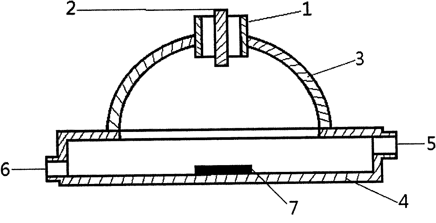
[0012] The microwave plasma resonant cavity of this embodiment: the inner diameter of the cylindrical waveguide input tube 1 is Ф50mm, the axial height is 20mm, the tube wall thickness is 2mm, and the material is stainless steel; The height of the bottom surface of the chamber 4 is 251.7mm, and the material is copper; the radius of curvature of the hemispherical metal chamber 3 is R295.6mm (R=2.42λ), and the height of the inner chamber (from the top of the hemispherical inner chamber to the outer top surface of the box-shaped metal chamber 4 distance) 221.7mm, the inner diameter of the lower port is Ф572.42mm, the thickness is 2mm, and the material is stainless steel; the box-shaped metal cavity 4. This embodiment adopts a square metal cavity with a side length of 300mm and an inner cavity height of 50mm. The diameter of the central hole on the top of the box body is the same as The diameter of the lower port of the hemispherical metal chamber 3 is the same as Ф572.42mm, and th...


PUM


Abstract

The invention belongs to a resonant cavity matched with a microwave plasma depositing device so as to be used for depositing the diamond film, which includes a resonant cavity body comprising a hemispherical metal cavity and a box-shaped metal cavity, a cylindrical wave-guide input pipe and a mode conversion antenna thereof, a depositing platform arranged on the bottom plane of the box-shaped inner cavity as well as a reaction gas inlet and a vacuum pump interface which are respectively arranged on two side walls of the cavity body. The inner spherical surface in the resonant cavity is equivalent to a concave mirror; however, the bottom surface of the box-shaped metal cavity is equivalent to a flat mirror; when microwave emitted by a magnetron is radiated into the resonant cavity through the mode conversion antenna and reflected backwards and forwards between the hemispherical inner wall and the bottom surface of the box-shaped cavity, most energy is centralized into the middle part ofthe inner cavity so as to excite stable large-area plasma; therefore, the microwave plasma resonant cavity used for depositing the diamond film has the characteristics that the simple structure is simple, which can effectively reduce the size of a system matched thereof, and cooling is convenient; the concentration ratio of the regions with stronger field strength is high and the area thereof islarger; moreover, the Q value of the cavity body is high, which is beneficial to depositing a large-area diamond film and improving the quality thereof, etc.

Description

technical field [0001] The invention belongs to microwave plasma vapor phase thin film deposition technology, in particular to a resonant cavity matched with a microwave plasma chemical vapor deposition device for depositing diamond thin films. Background technique [0002] At present, microwave plasma technology has been more and more widely used in many high-tech fields. Microwave Plasma Chemical Vapor Deposition (MPCVD), as a new type of technology, has received widespread attention and is mainly used in the fields of cutting tools, film coatings for molds, wear-resistant and heat-conducting materials, as well as optical materials, electronic materials and sensors. [0003] The preparation of diamond films by microwave plasma chemical vapor deposition technology is one of the most influential plasma technology applications. Diamond has extremely high hardness, extremely high thermal conductivity at room temperature, extremely low thermal expansion coefficient, high chemi...

Claims


Application Information

Patent Timeline
IPC IPC(8): H01J37/32H01J37/16C23C16/511
Inventor 曾葆青汪仁波
Owner UNIV OF ELECTRONICS SCI & TECH OF CHINA
Why Eureka
Try Eureka