
Epoxy protective coating system for high-power nuclear power station

A technology for protective coatings and nuclear power plants, applied in epoxy resin coatings, anti-corrosion coatings, coatings, etc., can solve problems that limit the application of high-power nuclear power plants, achieve excellent radiation protection performance, improve radiation resistance and decontamination performance, The effect of improving adhesion

Active Publication Date: 2010-07-21
CHINA NAT OFFSHORE OIL CORP +2
View PDF5 Cites 27 Cited by
  • Summary
  • Abstract
  • Description
  • Claims
  • Application Information

AI Technical Summary

Problems solved by technology

In short, none of the coatings involved in the above-mentioned patented technologies have excellent corrosion resistance and radiation resistance and have passed the simulated DBA test, which limits their application in high-power nuclear power plants

Method used


Image

  • Epoxy protective coating system for high-power nuclear power station

Examples

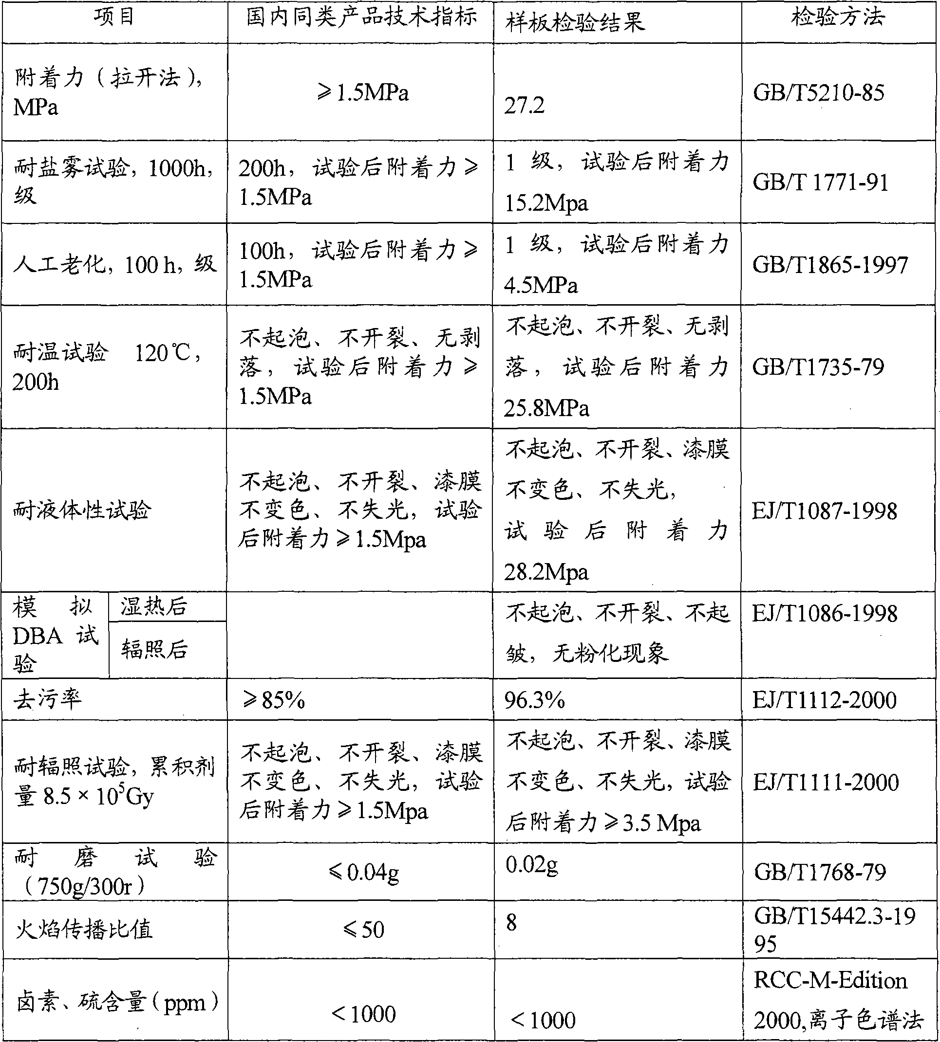

Embodiment 1

[0031] Embodiment 1 prepares component A1

[0032] 1. Formula

[0033] Component A1 is composed of 20%-50% of epoxy resin, 10%-40% of anti-corrosion pigment, 10%-25% of radiation-resistant filler, 0.1%-3% of auxiliary agent and solvent as the balance, and the above percentages are all by mass Percentage, the specific formula is shown in Table 1.

[0034] Table 1

[0035] component name

raw material name

Dosage, g

epoxy resin

Bisphenol A epoxy resin (E-44)

Bisphenol A type epoxy resin (E-20)

Bisphenol F epoxy resin (F-51)

5

9

9

Anti-corrosion pigment

iron yellow

Iron oxide red

barium metaborate

Zinc phosphate

10

3

15

9

Radiation resistant filler

talcum powder

Mica powder

5

5

fumed silica

1

Auxiliary

Dispersant (EFKA5054)

1

solvent

Xylene

Butanol

20

8

[0036] Note: The dispersant EF...

Embodiment 2

[0039] Embodiment 2 prepares component A2

[0040] 1. Formula

[0041] Topcoat component A2 is composed of 20%-50% of epoxy resin, 10%-40% of radiation-resistant pigment, 5%-20% of radiation-resistant filler, 0.1%-3% of auxiliary agent and solvent as the balance. The above percentages are all It is a mass percentage, and the specific formula is shown in Table 2.

[0042] Table 2

[0043] component name

raw material name

Dosage, g

epoxy resin

Bisphenol A epoxy resin (E-44)

Bisphenol A epoxy resin (E-04)

Bisphenol F epoxy resin (F-44)

8

7

18

[0044] component name

raw material name

Dosage, g

Anti-radiation pigment

Titanium dioxide

Nano Titanium Dioxide

25

2

Radiation resistant filler

Precipitated Barium Sulfate

talcum powder

9

5

Auxiliary

Leveling agent (EFKA3772)

1

solvent

Xylene

Butanol

18

7

[004...

Embodiment 3

[0048] Embodiment 3 preparation component B (radiation resistant epoxy-amine adduct curing agent)

[0049] 1. The raw materials used in the synthesis of radiation-resistant epoxy-amine adduct curing agent and the percentages of each raw material in the total mass of component B are as follows: 10% to 30% of liquid epoxy resin, multi-component epoxy resin with primary amine groups 30% to 70% of amine, 20% to 60% of solvent, the specific dosage is shown in Table 3.

[0050] table 3

[0051] component name

raw material name

Dosage, g

liquid epoxy resin

E-51

10

with primary amine groups

polyamine

triethylenetetramine

Polyamide No. 200

10

20

solvent

Xylene

Butanol

Propylene Glycol Methyl Ether

25

15

20

[0052] Note: Liquid epoxy resin E-51 can also be replaced by E-44;

[0053] 2. Specific operation method

[0054] In the reaction bottle equipped with stirring, adding system,...


PUM

PropertyMeasurementUnit
adhesivityaaaaaaaaaa
decontamination rateaaaaaaaaaa

Abstract

The invention relates to an epoxy protective coating system for a high-power nuclear power station. Priming coat comprises a component A1 and a component B with the weight ratio of 4-6, and finishing coat comprises a component A2 and the component B with the weight ratio of 3-5:1.. The component A1 comprises 20 to 50% of epoxy resin, 10 to 40% of anti-corrosion paint, 10 to 25% of radiation-resistant stuffing, 0.1 to 3% of addition agent and the balance of menstruum by weight percent. The component A2 comprises 20 to 50% of the epoxy resin, 10 to 40% of the anti-corrosion paint, 5 to 20% of the radiation-resistant stuffing, 0.1 to 3% of the addition agent and the balance of the menstruum by weight percent. The component B is a radiation-resistant epoxy-amine adduct curing agent, and is synthesized by 10 to 30% of liquid epoxy resin, 30 to 70% of polyamine with primary amine groups and 20 to 60% of the menstruum. The corrosion resistance and radiation resistance can meet the requirements of nuclear grade paint and can pass simulation DBA tests when the coating system is used for a high-power nuclear power station.

Description

technical field [0001] The invention relates to an epoxy protective coating system for high-power nuclear power plants, more specifically, an epoxy protective coating system for high-power nuclear power plants that has excellent corrosion resistance and radiation protection and has passed the simulated DBA test. Background technique [0002] With the global economic recession triggered by the world oil crisis, people are more aware of the important role of nuclear power in ensuring energy supply and suppressing energy market price fluctuations, and nuclear power has entered a stage of rapid development. As a safe, economical and clean energy with mature technology and large-scale production, nuclear power has a lot of room for development in the long-term planning of China and even the world. At the same time, with the advancement of nuclear power technology, the power generation of nuclear power plants has been greatly increased, from the original 300,000 kilowatts to the c...

Claims


Application Information

Patent Timeline
Patent Type & Authority Applications(China)
IPC IPC(8): C09D163/02C09D7/12C09D5/08G21F1/10
Inventor 王留方朱亚君张睿倪爱兵赵宝华刘志远移易
Owner CHINA NAT OFFSHORE OIL CORP
Learn More