Laser-induction hybrid melting direct forming method and device

A laser induction and direct technology, applied in the field of laser processing, can solve problems such as residual stress, low processing efficiency, and non-dense structure, and achieve the effects of improving hardness and wear resistance, reducing production cost, and high material utilization rate

Inactive Publication Date: 2011-09-14
HUAZHONG UNIV OF SCI & TECH
View PDF3 Cites 48 Cited by
  • Summary
  • Abstract
  • Description
  • Claims
  • Application Information

AI Technical Summary

Problems solved by technology

[0004] However, the above-mentioned forming method using a simple laser beam as a heat source for melting and depositing metal materials has the following disadvantages: 1. the processing efficiency is low: when the Nd:YAG laser is used, and the laser power is 3-12KW, the powder deposition rate is only 15- 40g/min (taking iron-based alloys as an example); ② Due to the large temperature gradient between the laser molten pool and the substrate, large residual stress is caused, resulting in deformation and cracking of parts, which has become a bottleneck restricting the application of this technology; ③ Due to the "thermal Accumulation effect", the thermal process between different deposition layers is different, resulting in uneven structure and mechanical properties, affecting its performance; ④ Due to its

Method used


Image

  • Laser-induction hybrid melting direct forming method and device
  • Laser-induction hybrid melting direct forming method and device
  • Laser-induction hybrid melting direct forming method and device

Examples


Embodiment 1

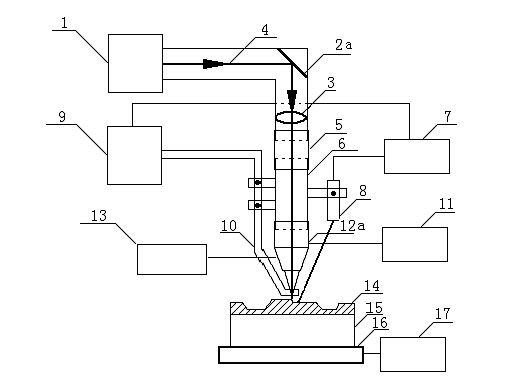
[0059] Using laser-induction compound melting forming method and device to prepare large and medium-sized punching dies, as attached figure 1 shown. The composite layer of Ni-based alloy and WC is generated layer by layer on the Q235 steel substrate through CAD layering software and numerical control system control. The mass percentage of WC powder is gradually increased from 0-60% to obtain gradient composition. The thickness of the forming layer ranges from 2-500mm, its hardness is 60-70HRC, and its wear resistance is 15-30 times that of the base material.

[0060] Implementation steps:

[0061] ① Clean the annealed substrate after derusting, and clamp it on the horizontal platform of the CNC machine tool.

[0062] ② Turn on the 5KW cross-flow CO2 laser. The laser beam is directed into the focusing lens through the reflective copper mirror and then vertically incident on the substrate. Adjust the defocus amount of the laser beam so that the diameter of the spot is 6mm. ...

Embodiment 2

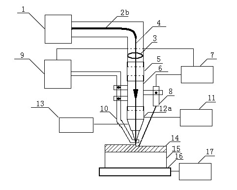
[0071] Using laser-induction compound melting forming method and device to prepare large and medium-sized hot hammer forging dies, as attached figure 2 shown. Through CAD layered software and numerical control system control, cobalt-based alloy deposits are formed layer by layer on the H13 steel substrate. The thickness of the forming layer ranges from 5-20mm, and its hardness is 45-55HRC. The thermal strength and fatigue resistance are greater than that of the substrate. increase in magnitude.

[0072] Implementation steps:

[0073] ① Clean the annealed H13 steel matrix after derusting, and clamp it on the horizontal platform of the CNC machine tool.

[0074] ②Turn on the 4KW high-power semiconductor laser, and the laser beam is focused by the optical fiber into the focusing lens and then vertically incident on the substrate. Adjust the defocus amount of the laser beam so that the diameter of the spot is 10mm.

[0075] ③The induction coil is installed on the lifting slee...

Embodiment 3

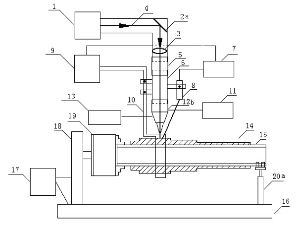
[0083] Hollow shaft parts are prepared by laser-induction compound melting forming technology and device. as attached image 3 As shown, the ordinary hollow steel pipe is used as the base. The steel pipe has an outer diameter of 200 mm and a wall thickness of 5 mm. A gradient metal-ceramic composite layer is formed on the substrate. The thickness of the forming layer ranges from 2-500mm, the hardness after forming is 60-70HRC, and the wear resistance is 10-30 times higher than that of the matrix.

[0084] Implementation steps:

[0085] ① Clamp the cleaned and sandblasted substrate on the three-jaw chuck and rolling bracket on the horizontal platform of the CNC machine tool.

[0086] ②A 15KW cross-flow CO2 laser is used. Adjust the defocus of the laser beam so that the light spot is a rectangle of 3mm×20mm, and the long side of the light spot is parallel to the axis of the substrate.

[0087] ③The induction coil is fixed by the clamp and the sleeve. Make the induction co...


PUM

PropertyMeasurementUnit
Thicknessaaaaaaaaaa
Thicknessaaaaaaaaaa
Outer diameteraaaaaaaaaa

Abstract

The invention discloses a laser-induction hybrid melting direct forming method and device. The laser-induction hybrid melting direct forming method comprises the following steps of: generating a three-dimensional model of a part through CAD (Computer-Aided Design) software, and then slicing the three-dimensional model and generating a G code to drive a numerical control system and a base body to move; and melting synchronously fed metal or metal/ceramic hybrid powder through a high-power laser beam and an induction heat source, and depositing the three-dimensional part in a designed shape layer by layer, wherein a temperature controller is used for monitoring and controlling the temperature of the base body in the processing process. The device for realizing the laser-induction hybrid melting direct forming method comprises a laser, a light path system, an induction heating and temperature control system, a powder feed system and the numerical control system. The device can be used for directly generating large and medium size three-dimensional parts on various metal base bodies, has the advantages of high processing efficiency, compact part structure, fine crystalline grain, excellent mechanical property, less residual stress without deformation or cracking phenomenon, high processing flexibility without tools and moulds, high material utilization ratio, cleanness without pollution and capability of designing the components of a metal-ceramic hybrid layer as required and even changing the components in a gradient manner.

Description

technical field [0001] The invention belongs to the field of laser processing. Specifically, it relates to a method and a device for preparing three-dimensional metal parts by laser-induction hybrid melting direct forming (Laser-Induction Hybrid Melting Direct Forming, LIHMDF). Background technique [0002] Direct Laser Fabrication (DLF) technology is an advanced manufacturing technology developed in the middle and late 1990s. The basic principle is to generate the CAD model of the part with the help of CAD software or reverse technology, and then use the forming control software to cut the CAD model into a series of parallel sheets at a certain distance, and then design a reasonable laser scanning trajectory according to the outline of the sheet, and convert it into CNC System motion commands. The laser beam scans the substrate under command control, melts the powder delivered by the powder feeder, and deposits a thin metal layer that is basically consistent with the thic...

Claims


Application Information

Patent Timeline
IPC IPC(8): B22F3/105
Inventor 曾晓雁王邓志胡乾午王泽敏马明明
Owner HUAZHONG UNIV OF SCI & TECH
Why Eureka
Try Eureka