A process method and device for manufacturing polymer ceramic pipeline lining

A technology of polymer ceramic and process method, which is applied in the field of technology and device for manufacturing polymer ceramic pipeline lining

Inactive Publication Date: 2011-12-14
袁茂豪
View PDF3 Cites 2 Cited by
  • Summary
  • Abstract
  • Description
  • Claims
  • Application Information

AI Technical Summary

Problems solved by technology

[0002]With the rapid development of economy, the demand for oil and natural gas fuels has increased rapidly, and the exploitation of oil has changed from high oil content to high water content now. The oil content of the pumped crude oil has reached 80%-90%, and now most of the crude oil contains only 20%-35%. Due to the continuous decline of oil content, the water vapor in the oil and gas pipelines of oil production wells and pressurized water wells will , hydrogen sulfide, carbon dioxide, calcium oxide and other substances increased, the problems of pipeline corrosion, scaling and perforation, and eccentric wear of oil production pipes became more and more serious, making the frequency of pipe replacement more and more high, and the reported damage of pipelines was quite serious, which caused serious damage to enterprises. caused huge economic losses and brought great harm to the society
At present, the main methods used to deal with these problems in oil (gas) pipelines are as follows. Although these methods have some advantages, they have the following problems: 1. For example, using HDPE (high-density polyethylene) inner The liner is used as an oil pipe lining, and its disadvantage is that it cannot withstand high temperatures. The embrittlement temperature of HDPE (high-density polyethylene) is about 75 degrees, and the melting point is 130 degrees, while most of the downhole temperatures are above 100 degrees. .And it is not wear-resistant at a certain temperature; 2, such as the self-diffuse combustion method lining pipelines invented by domestic key universities. This method can only be used for large-scale pipelines, and the thickness of the lining should not be less than 6-8mm. And During its cooling, most of the sheets will be split. The second is that the high temperature generated by combustion will cause the pipe to be deformed by heat. Therefore, when processing the inner lining, a stretching device must be used to make the internal supplementary processing while the pipe is being stretched. Otherwise, The inner lining will be uneven and fail to meet the technical requirements. At the same time, the device used in this method consumes a lot of energy; 3. For example, the method of spraying alloy materials uses a mixture of resin and alloy materials to spray on the inner wall of the pipe through high-pressure airless spraying for anti-corrosion treatment. The process method not only requires the viscosity of the paint to be very strict, but also has high requirements on the construction environment and climate. The process is complicated, the operation is inconvenient, and the efficiency is low. tight, the lining is easy to break and fall off, the resin is easy to soften under high temperature, and because the alloy layer is too hard, the oil production rod is easy to wear out; 4, such as the electroplating alloy method, because the cost is too high, it cannot meet the market requirements 5. Aiming at the problems existing in the above-mentioned prior art, especially the problem that the technical requirements for oil pipes within 100 mm cannot be met, the applicant applied for an application number on March 30, 2010 2010101379040 is mainly used to manufacture the process and device of ceramic pipeline lining within 100 meters. This application adopts the method of forming and solidifying the lining of the pipeline ceramic pipeline when it rotates at high speed under heating conditions. The structure of this device is relatively complicated and the production cost is relatively high. Height and uneven lining of pipes

Method used


Image

  • A process method and device for manufacturing polymer ceramic pipeline lining
  • A process method and device for manufacturing polymer ceramic pipeline lining
  • A process method and device for manufacturing polymer ceramic pipeline lining

Examples


Embodiment 1

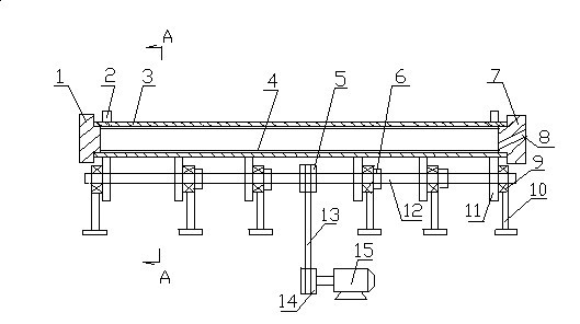
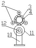
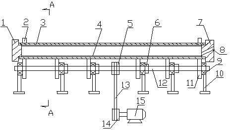
[0022] Example 1, the silica powder with a weight ratio of 80% and a fineness of 200-500 meshes is first mixed with polyamide in a container with a weight ratio of 2%, and then placed in the container within 5 minutes before making the lining. Add epoxy resin powder with a weight ratio of 18% to the mixture and stir and mix it for three minutes to form an enamel paint. Calculate the amount of enamel paint added according to the length, thickness and specific gravity of the inner lining 4. The pipeline is assembled on six driving wheels 11 arranged at intervals. , first seal and fix one end of the pipeline 3 with the left sealing head 1, then add a certain amount of varnish into the pipeline through the feeding hole 8 on the right sealing head 7 within a specified time, and then seal the two ends of the pipeline, the length of the pipeline is 9.6 meters, the inner diameter of the pipeline is 62 mm, and there are two adjustable limit wheels 2 that are symmetrically arranged aroun...

Embodiment 2

[0023] Example 2, the aluminum oxide powder with a weight ratio of 86% and a fineness of 1000-2500 meshes is pre-mixed with ethylenediamine in a container with a weight ratio of 0.3%, and then within 5 minutes before making the lining Add phenolic resin powder with a weight ratio of 13.7% and molybdenum sulfide of 2% of the total weight of the above three raw materials into the container and mix them thoroughly for three minutes to form an enamel paint. Calculate the amount of enamel paint added according to the length, thickness and specific gravity of the inner lining. The pipeline The length is 10 meters, and the inner diameter of the pipeline is 62 millimeters. The device and manufacturing process described in Example 1 are used to complete the coating, molding and curing of the pipeline lining. After testing, the thickness of the lining is between 1.2 and 1.5 mm (one side), the maximum thickness deviation is 0.3 mm, and the maximum error rate is 0.3 per ten thousand. The c...

Embodiment 3

[0024] Example 3 Pre-mix zirconium silicate with a weight ratio of 72% and a fineness of 600-1000 mesh with 4% diethylenetriamine in a container, and then mix it in the container within 5 minutes before making the inner liner. Add phenolic resin powder with a weight ratio of 14% and silicone oil of 3% of the total weight of the above three raw materials to fully mix for three minutes to form an enamel paint. Calculate the amount of enamel paint added according to the length, thickness and specific gravity of the lining. The length of the pipeline is 9.6 meters. The inner diameter of the pipeline is 62 mm, and the coating, molding and curing of the pipeline lining are completed by using the device and manufacturing process described in Example 1. After testing, the thickness of the lining is between 1.3 and 1.6 mm (one side), the maximum thickness deviation is 0.3 mm, and the maximum error rate is 0.3 per ten thousand. The compressive strength of the lining is 269 MPa, and the V...


PUM

PropertyMeasurementUnit
Vickers hardnessaaaaaaaaaa
thicknessaaaaaaaaaa
compressive strengthaaaaaaaaaa

Abstract

The present invention separates a process method for manufacturing polymer ceramic pipeline lining, which is mainly composed of 70-90%wt ceramic powder, 5-25%wt polymer material and 0.1-5%wt curing agent raw material, First, mix and stir the above raw materials to form the enamel paint, calculate the amount of enamel paint added according to the length, thickness and specific gravity of the pipeline lining, add the enamel paint to the pipeline that is sealed and supported on the driving wheel, and the motor drives the driving wheel to make the pipeline in Rotate slowly and then quickly at 100 to 1000 rpm. During the rotation, the enamel paint is coated, formed and cured. The lining of the present invention not only has good strength, high hardness, high temperature resistance and corrosion resistance, but also has a uniform thickness. , dense, smooth and wear-resistant, long service life. At the same time, the device is compact and simple in structure, easy to operate, high in enamelling efficiency, and can realize large-scale production. Urban pipe lining processing.

Description

technical field [0001] The invention relates to a manufacturing process and a device for oil recovery, gas recovery, pressurized water wells, gas transmission and chemical pipeline linings. Background technique [0002] With the rapid development of the economy, the demand for oil and natural gas fuels has increased rapidly. The extraction of oil has changed from high oil content to the current high water content. The oil content of the crude oil pumped up before has reached 80%-90%. The oil content of most crude oil is only 20%-35%. Due to the continuous decline of oil content, water vapor, hydrogen sulfide, carbon dioxide, calcium oxide, etc. Scaling, perforation, and eccentric wear of oil production pipes are becoming more and more serious, making the frequency of pipe replacement more and more high, and the reported damage of pipes is quite serious, causing huge economic losses to enterprises and great harm to society . At present, the main methods used to deal with th...

Claims


Application Information

Patent Timeline
Patent Type & Authority Applications(China)
IPC IPC(8): C23D5/00
Inventor 袁茂豪于武昌袁超袁君杨绍军周承武
Owner 袁茂豪
Why Eureka
Try Eureka