Organic solar cell

A solar cell, organic technology, applied in circuits, photovoltaic power generation, electrical components, etc., can solve problems such as low efficiency, achieve the effect of improving transmission and collection efficiency, reducing series resistance, and improving interface contact performance

Inactive Publication Date: 2012-07-18
NANJING UNIV OF POSTS & TELECOMM
View PDF4 Cites 7 Cited by
  • Summary
  • Abstract
  • Description
  • Claims
  • Application Information

AI Technical Summary

Problems solved by technology

The biggest application bottleneck of organic

Method used


Image

  • Organic solar cell
  • Organic solar cell
  • Organic solar cell

Examples


Embodiment 1

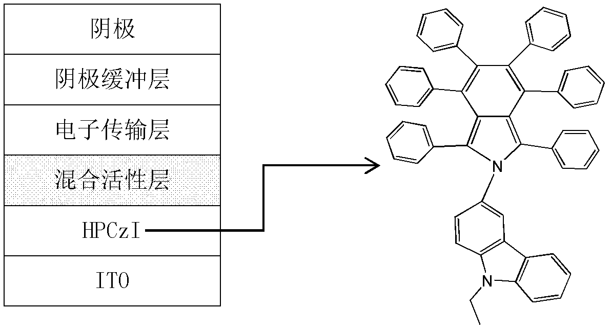
[0029] Organic solar cells were evaporated on a cleaned ITO glass substrate (sheet resistance of 15 Ω / □). The ITO glass substrate was washed with detergent, acetone, isopropanol and deionized water for 30 minutes, and then heated at 120°C. Bake for at least 10 minutes, before evaporating the organic layer, and then use O 2 Plasma treatment for 50 seconds. Organic material is at 3.5 x 10 -4 It is vacuum evaporated under the pressure of Pa, and the vacuum when evaporating cathode aluminum is 2×10 -3 Pa. The ITO substrate was at room temperature during evaporation, and HPCzI was sublimated and purified before use. The purity of C60 used in the experiment reached 99.9%. The evaporation rate of HPCzI is about 1 ? / s, the photoactive layer is CuPc and C60 co-evaporation, the evaporation rate is 0.25 ? / s at the mixed concentration of 1:1, and the evaporation rate of electron transport layer C60 is about 0.45 ? / s, the evaporation rate of TPBi is 0.55 ? / s, and the evaporation rat...

Embodiment 2

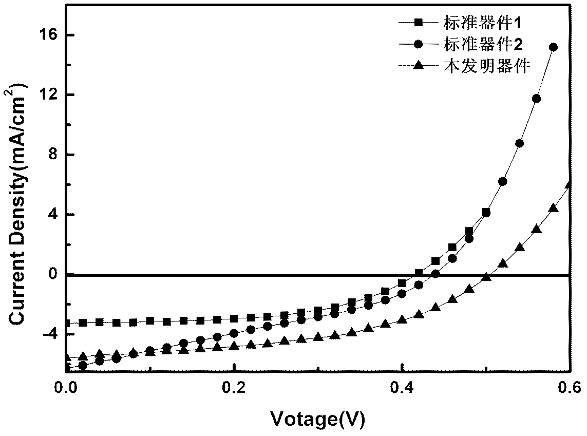
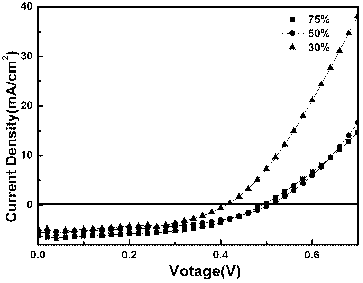
[0038] This example shows the short-circuit current, open-circuit voltage, fill factor and power efficiency of the device when HPCzI and CuPc materials are used as the anode buffer layer respectively, and the CuPc concentration in the mixed photoactive layer is 30%, 50%, and 75%.

[0039] Standard device structure: glass substrate / ITO / CuPc (150 ?) / CuPc: C60 (250 ?) / C60 (200 ?) / TPBi (80 ?) / Al (1000 ?).

[0040] The device structure of the present invention: glass substrate / ITO / HPCzI (150?) / CuPc: C60 (250?) / C60 (200?) / TPBi (80?) / Al (1000?).

[0041] Table 2 shows the corresponding values ​​of short-circuit current, open-circuit voltage, power efficiency and fill factor of devices of the present invention and standard devices with different CuPc doping concentrations. It can be seen from Table 2 that the device efficiency of the device of the present invention is higher than that of the standard device when the CuPc concentration is 30%, 50%, and 75%.

[0042] Table ...


PUM


Abstract

The invention discloses an organic solar cell structure which is based on a 1,3,4,5,6,7-hexaphenyl-2-3'-(9'-ethylcarbazolyl)-isoindole [HPCzI] material. The structure comprises a substrate, an anode, an anode buffering layer, a hole transport layer, a mixed photoactivity layer, an electronic transport layer, a cathode buffering layer and a cathode in sequence from down to up, wherein the substrate is made of transparent materials such as quartz plates, glass sheets, polystyrene or polyethylene and the like, the anode is made of metal, metallic oxide, carbon black or conducting polymer and the like, whose work functions are all more than that of the cathode, the anode buffering layer and the hole transport layer are made of the HPCzl, the mixed photoactivity layer is made of an organic donor material and an organic receptor material which are mixed, such as CuPc or AnPc which is mixed with C60 or PCBM (fullerene derivatives), the electronic transport layer is made of organic electronic transport materials such as C60 and the like, the cathode buffering layer is made of TPBi, BCP, BPhen, LiF and the like, and the cathode is made of metal or metal alloy, whose work function is relatively lower than that of the anode. Except the anode, all the layers are prepared in a way that organic films are deposited by vacuum vapour plating, spraying, printing and the like. The organic solar cell structure is beneficial for improving power converting efficiency of an organic solar cell.

Description

technical field [0001] The invention relates to the technical field of organic photoelectric devices, in particular to a 1,3,4,5,6,7-hexaphenyl-based [0002] Novel organic solar cell structures based on 2-3'(9'-ethylcarbazolyl)-isoindole [HPCzI] materials. The structure prepares an organic solar cell with high power efficiency by using the HPCzI material as the anode buffer layer and the hole transport layer of the organic solar cell. Background technique [0003] Today, when fossil energy sources such as coal, oil, and natural gas are in short supply and the ecological environment is deteriorating, solar energy has become a new generation of energy stars with its advantages of being renewable, green, pollution-free, and low-cost. The research on solar cells began in the 1950s, mainly focusing on inorganic solar cells with monocrystalline silicon as the active material. At that time, the device efficiency (PEC) reported by Bell Labs was 4%. At present, the total energy co...

Claims


Application Information

Patent Timeline
IPC IPC(8): H01L51/46H01L51/42
CPCY02E10/549
Inventor 密保秀高志强黄维李欣汪红娇
Owner NANJING UNIV OF POSTS & TELECOMM
Why Eureka
Try Eureka