Polymer solar cell

A technology of solar cells and polymers, applied in the field of solar cells, can solve the problems of low energy conversion efficiency and low conductivity of polymer solar cells, and achieve the effects of facilitating electron transmission and collection, increasing short-circuit current, and increasing conductivity.

Active Publication Date: 2013-09-04
CHANGCHUN INST OF APPLIED CHEMISTRY - CHINESE ACAD OF SCI
View PDF1 Cites 6 Cited by
  • Summary
  • Abstract
  • Description
  • Claims
  • Application Information

AI Technical Summary

Problems solved by technology

[0004] In order to solve the problem of low energy conversion efficiency of polymer solar cells caused by the low conductivity of electron transport layer materials in the prior art, the present invention provides a cathode interface layer based on zinc oxide nanocrystals and conjugated polymer composites. polymer solar cell

Method used


Image

  • Polymer solar cell
  • Polymer solar cell
  • Polymer solar cell

Examples


preparation example Construction

[0031] The preparation process of the inverted structure polymer solar cell comprises the following steps:

[0032] forming a cathode layer 2 on the substrate 1;

[0033] A composite of zinc oxide-phosphate polyfluorene is used on the above-mentioned cathode layer 2 to form a cathode interface layer 3;

[0034] Prepare a blend of conjugated polymers and fullerene derivatives on the cathode interface layer 3 to form a photosensitive layer 4;

[0035] On the photosensitive layer 4, an anode interface layer 5 and an anode layer 6 are sequentially evaporated to obtain a polymer solar cell.

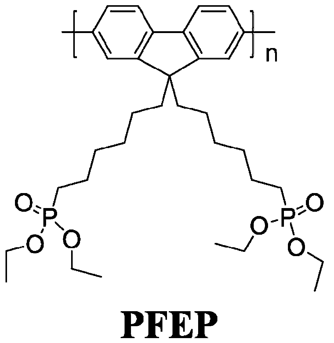
[0036] The substrate 1 is a rigid or flexible substrate, the cathode layer 2 is indium tin oxide (ITO), the cathode interface layer 3 is a zinc oxide-phosphoester polyfluorene hybrid material, and the ZnO-PFEP composite cathode interface layer 3 The mass ratio of ZnO to PFEP ranges from 100:1 to 1:100, most preferably 6:1.

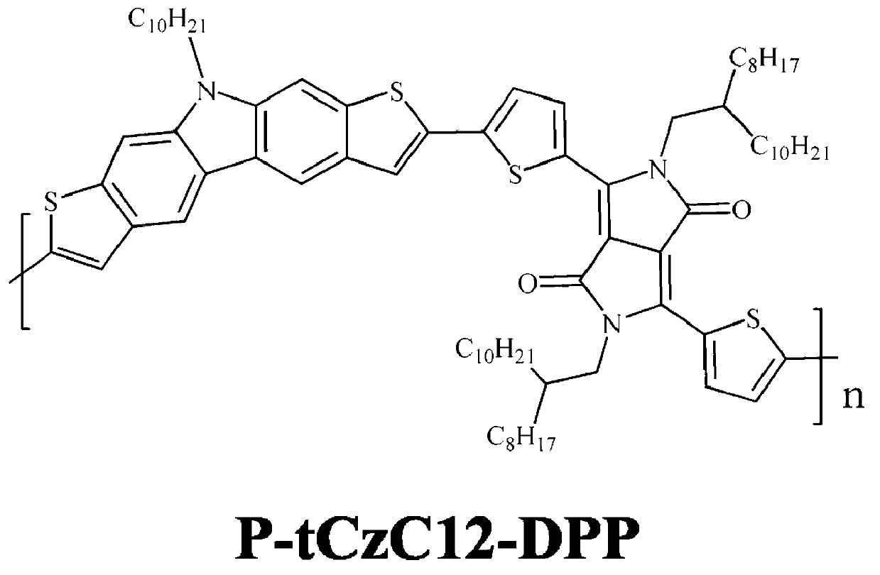
[0037] The photosensitive layer 4 is a blend of conjugated polymer...

Embodiment 1

[0052] (1) The etched glass substrate 1 with thin strip-shaped ITO cathode layer 2 is cleaned and dried, then placed on the bracket of the coating machine, and the stirred ZnO-PFEP mixed solution is passed through 0.45 micron The filter head is evenly coated on the top of the cathode layer ITO, and the coating film is rotated at a speed of 300 rpm to obtain a cathode interface layer 3 with a thickness of 100 nanometers; the ZnO-PFEP mixed solution is obtained by adding 30 mg of zinc oxide ( ZnO) and 5 mg phosphate polyfluorene (PFEP) were dissolved in 1 ml of n-butanol solvent, and the mixed solution obtained after magnetic stirring for 12 hours;

[0053] (2) Spin coating The substrate coated with the cathode interface layer 3 is placed on the carriage of the coating machine, and the stirred poly[2,8-N-dodecyldithieno[3,2 -b;6,7-b]carbazole-alt-3,6-bis(thiophen-2-yl)-2,5-bis(2-octyldodecyl)pyrrolo[3,4-c ]pyrrole-1,4-dione](P-tCzC12-DPP) with PC 70 The mixed solution of BM is...

Embodiment 2

[0058] (1) The etched glass substrate 1 with thin strip-shaped ITO cathode layer 2 is cleaned and dried, then placed on the bracket of the coating machine, and the stirred ZnO-PFEP mixed solution is passed through 0.45 micron The filter head is evenly coated on the top of the cathode layer ITO, and the coating film is rotated at a speed of 7000 rpm to obtain a cathode interface layer 3 with a thickness of 1 nanometer; the ZnO-PFEP mixed solution is obtained by adding 100 mg of zinc oxide ( ZnO) and 1 mg of phosphate polyfluorene (PFEP) were dissolved in 100 ml of n-butanol solvent, and the mixed solution obtained after magnetic stirring for 12 hours;

[0059] (2) Spin coating The substrate 1 coated with the cathode interface layer 3 is placed on the carriage of the coating machine, and the stirred P-tCzC12-DPP and PC 70 The mixed solution of BM is evenly coated on the above-mentioned ZnO / PFEP cathode interface layer 3, and the coating film is rotated at a speed of 3000 rpm to ...


PUM

PropertyMeasurementUnit
Thicknessaaaaaaaaaa
Thicknessaaaaaaaaaa
Thicknessaaaaaaaaaa

Abstract

The invention relates to a polymer solar cell. The polymer solar cell sequentially comprises a cathode layer, a cathode interface layer, a photosensitive layer, an anode interface layer and an anode layer, wherein the cathode interface layer is an inorganic semiconductor nanocrystalline-conjugated polymer composite material layer. The cathode interface layer is specifically a ZnO-PFEP (phosphate ester polyfluorene) composite material layer. According to the polymer solar cell, the ZnO-PFEP composite cathode interface layer is arranged between the cathode layer and the photosensitive layer, and the mass ratio of ZnO to PFEP in the interface layer is controlled, so that the electrical conductivity of the cathode interface layer can be effectively increased, the bulk resistance of the cathode interface layer is reduced, the electron output resistance is decreased, furthermore, the short-circuit current, open-circuit voltage, fill factor and energy conversion efficiency of the cell are improved, and the electron transportation and collection are benefited.

Description

technical field [0001] The invention belongs to the technical field of solar cells, in particular to a polymer solar cell. Background technique [0002] Polymer solar cells have the advantages of low cost, good flexibility, light weight, and large-area processing, and have become a research hotspot in this field in recent years. Bulk heterojunction polymer solar cells can effectively improve the energy conversion efficiency of the cell due to the increase of the contact area between the electron donor and the electron acceptor. Traditional bulk heterojunction polymer solar cells generally use a positive sandwich structure, that is, high work function indium tin oxide (ITO) as the anode, low work function metal aluminum (Al) as the cathode, composed of polymer and fullerene A photosensitive layer formed from a blend of alkenes is sandwiched between the anode and cathode. In order to form an ohmic contact at the interface between the anode and the cathode, improve the collec...

Claims


Application Information

Patent Timeline
IPC IPC(8): H01L51/42H01L51/46H01L51/48
CPCY02E10/549
Inventor 谢志元耿延候邓云峰刘剑吴江
Owner CHANGCHUN INST OF APPLIED CHEMISTRY - CHINESE ACAD OF SCI
Why Eureka
Try Eureka