
Light-reflecting anisotropically conductive adhesive and light emitting device

A conductive adhesive, anisotropic technology, used in conductive adhesives, adhesives, conductive materials, etc., can solve the problems of luminous efficiency (reduced light extraction efficiency, reduced total luminous flux of reflectivity, etc.), and achieve chip shear strength. The effect of reducing the wavelength dependence and improving the luminous efficiency

Active Publication Date: 2013-11-27
DEXERIALS CORP
View PDF8 Cites 7 Cited by
  • Summary
  • Abstract
  • Description
  • Claims
  • Application Information

AI Technical Summary

Problems solved by technology

Thus, in Figure 4 In the light-emitting device of the above LED element 33, since the light emitted above the LED element 33 is not absorbed by the gold wire, most of the light emitted downward is reflected by the reflective layer 40 and emitted above, so the luminous efficiency (light extraction efficiency) does not decrease.
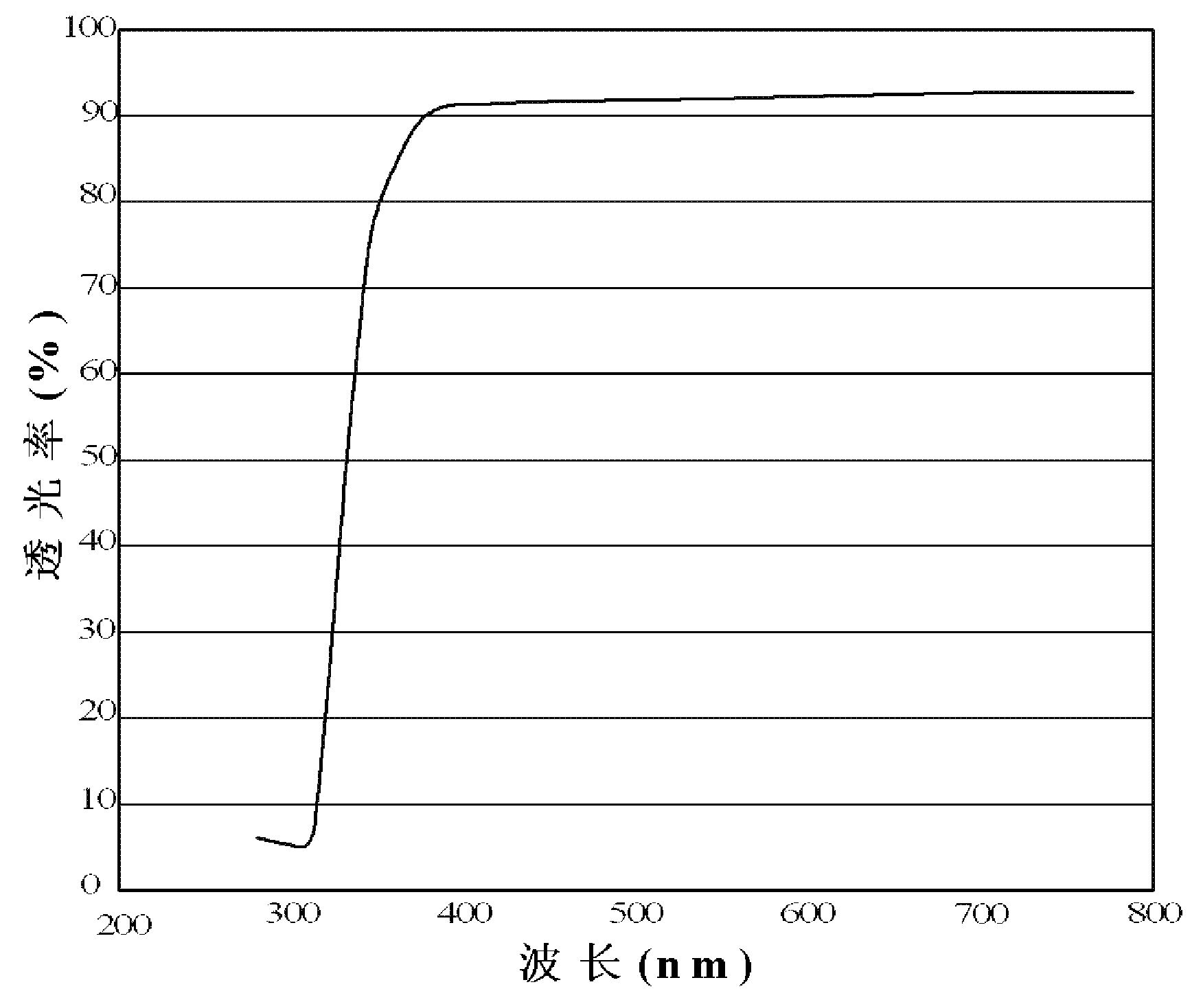
[0004] In addition, as a binder resin blended in the anisotropic conductive paste or anisotropic conductive film used to anisotropically connect the LED and the substrate, it is widely used to have relatively good heat resistance, light resistance and epoxy resin for connection reliability (patent document 2), but the epoxy resin is as in its molecular structure Figure 5A Light absorption occurs from the near-ultraviolet wavelength region to the near-infrared region, and if heat or light is applied for a long time (for example, continuous UV irradiation at 120°C), the molecular chain will be broken or oxidized, such as Figure 5B As shown by the arrow in , the light transmittance spectrum changes greatly, and there is a problem that the light reflectance and the total luminous flux of the LED are greatly reduced due to the long-term use of the light emitting device

Method used


Image

  • Light-reflecting anisotropically conductive adhesive and light emitting device
  • Light-reflecting anisotropically conductive adhesive and light emitting device
  • Light-reflecting anisotropically conductive adhesive and light emitting device

Examples


Embodiment 1~7

[0090] Embodiment 1~7, comparative example 1~4

[0091] A thermosetting resin composition was prepared by uniformly mixing the components in the compounding amounts (parts by mass) shown in Table 1 except for the conductive particles and the light-reflective insulating particles using an ordinary stand mixer. 10phr [parts per hundred resin] of Au particles and 30phr of light-reflective insulating particles were added to this thermosetting resin composition, and uniformly mixed with a stand mixer to obtain a white-looking light-reflective anisotropic conductive adhesive.

Embodiment 6

[0093] (Titanium oxide-coated silver particles (reflective insulating particles) used in Example 6)

[0094] 5g of granular silver particles (average particle diameter of 1.0 μm) and 50ml of toluene were dropped into the flask attached to the mixer, and 0.25g of silane coupling agent (3-methacryloxypropane) was dropped into the flask while stirring. Triethoxysilane), stirred at 25°C for 60 minutes. Then, 2 g of methyl methacrylate, 2 g of 2-hydroxyethyl methacrylate, 0.04 g of benzoyl peroxide and 1 g of 2,4-toluene diisocyanate were added to the mixture, and the After stirring for 12 hours, insulating-coated silver particles were obtained as light-reflective insulating particles. The average particle diameter of the light-reflective insulating particles including the insulating coating was 5.0 μm.

Embodiment 7

[0095] (Titanium oxide-coated gold particles (reflective conductive particles) used in Example 7)

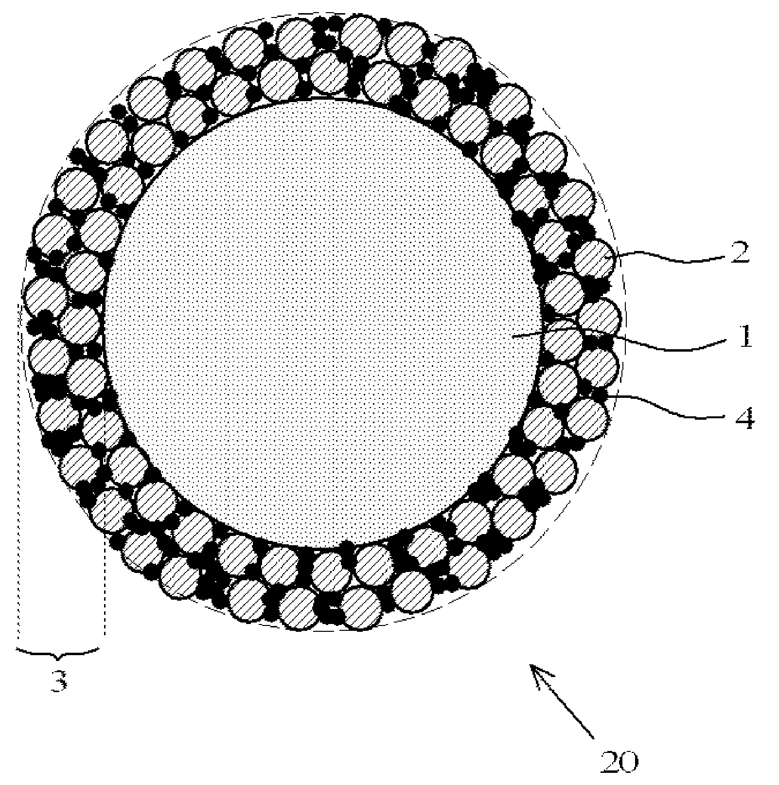
[0096] Titanium oxide powder with an average particle size of 0.5 μm and Au-coated resin conductive particles with an average particle size of 5 μm in brown color (spherical acrylic resin particles with an average particle size of 4.6 μm were subjected to electroless gold plating with a thickness of 0.2 μm) The obtained particles) were put into a mechanical fusion device, and a light-reflective layer of about 0.5 μm thick made of titanium oxide particles was formed on the surface of the conductive particles to obtain light-reflective conductive particles. The appearance color of the reflective conductive particles is gray.

[0097]


PUM

PropertyMeasurementUnit
particle diameteraaaaaaaaaa
diameteraaaaaaaaaa
particle diameteraaaaaaaaaa

Abstract

A light-reflecting anisotropically conductive adhesive, which is used for the purpose of making an anisotropically conductive connection of a light emitting element to a wiring board, contains: a thermosetting resin composition that contains a silicone resin and a curing agent; conductive particles; and light-reflecting insulating particles. The light-reflecting insulating particles are inorganic particles of at least one substance that is selected from the group consisting of titanium oxide, boron nitride, zinc oxide, silicon oxide and aluminum oxide. The silicone resin is a glycidyloxyalkyl-alicyclic alkyl-modified organopolysiloxane.

Description

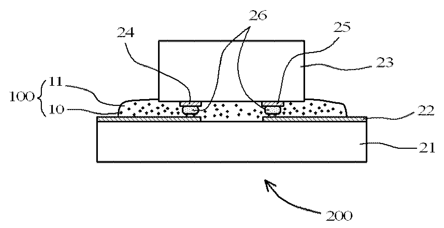
technical field [0001] The present invention relates to a reflective anisotropic conductive adhesive for anisotropically conductively connecting a light-emitting element to a wiring board, and a light-emitting device in which a light-emitting element is mounted on a wiring board using the adhesive. Background technique [0002] Light-emitting devices using light-emitting diode (LED) elements are widely used, and old-fashioned light-emitting devices have structures such as image 3 As shown, the LED element 33 is bonded on the substrate 31 with a die-bonding adhesive 32, and the p-electrode 34 and the n-electrode 35 on it are wire-bonded to the connection terminal 36 of the substrate 31 with a gold wire 37. Above, the whole LED element 33 is packaged with a transparent molding resin (transparent molding resin) 38 . But when image 3 In the case of a light-emitting device, in the light emitted by the LED element 33, the gold wire 37 absorbs the light emitted from the upper sur...

Claims


Application Information

Patent Timeline
Patent Type & Authority Applications(China)
IPC IPC(8): C09J183/04C09J9/02C09J11/04C09J11/06H01B1/00H01B1/20H01B5/16H01L33/60
CPCC08K2003/2241H01L2224/73265H01L2224/73204H01L2224/45144H01L2224/32225H01L33/62C08K5/0025C09J183/06H01B3/00H01L33/60H01L2224/48091C09J9/02H01L2224/16225H01L33/46C08G77/38C08G77/12C08K2003/2296H01L2224/48227C08K5/09H01B1/22H01L2924/07811H01L2924/00H01L2924/00014C09J183/04C09J11/04H01B1/00H01B1/20H01B5/16
Inventor 马越英明波木秀次青木正治石神明蟹泽士行
Owner DEXERIALS CORP
Learn More