Delayed coking method

A delayed coking method and a technology of salt compounds, which are applied in the delayed coking field, can solve the problems of reducing the quality of petroleum coke, increasing the ash content of petroleum coke, and high desulfurization cost, reducing investment costs and operating costs, increasing the depth of cracking reaction, and reducing coke. The effect of yield

Active Publication Date: 2014-02-12
CHINA PETROCHEMICAL CORP +1
View PDF5 Cites 6 Cited by
  • Summary
  • Abstract
  • Description
  • Claims
  • Application Information

AI Technical Summary

Problems solved by technology

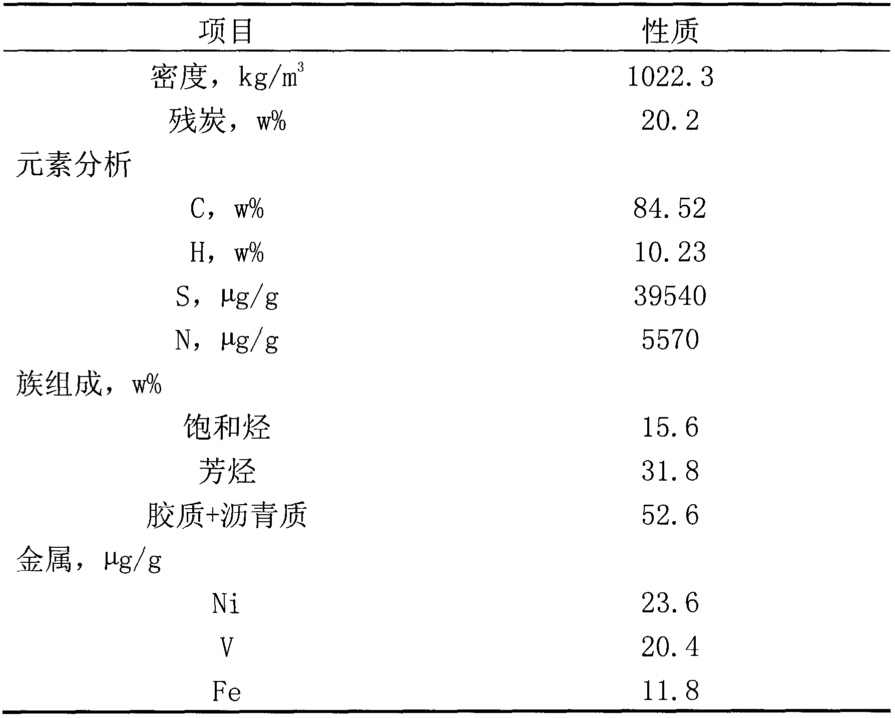
(1) Low liquid yield and high coke yield
(2) Coke with high sulfur content and poor quality
(3) The coking of the heating furnace tube is serious, which affects the long-term operation and processing capacity of the device
(1) Hydrogen is required, and catalytic cracking catalyst powder or metal oxides or sulfides are gathered in petroleum coke, increasing the ash content of petroleum coke and reducing the quality of petroleum coke; (2) increasing liquid yield, reducing coke yield and coke The sulfur content cannot be achieved at the same time; (3) After-treatment of petroleum coke to reduce the sulfur content, high-temperature calcination not only requires high energy consumption, but also requires the use of expensive high-temperature-resistant materials, and the cost of desulfurization is very high

Method used


Image

  • Delayed coking method
  • Delayed coking method

Examples


Embodiment 1

[0022] Weigh 50g of carbon black with a particle size of 60 μm and 1.0g of sodium carboxymethyl cellulose in beaker 1, and mix evenly; account for 1.0% of the weight of carbon black before modification according to the neodymium content, weigh 1.40g of neodymium in beaker 2 The content is 36% neodymium nitrate and 100g distilled water, stir to make it fully dissolved, then add the mixture of carbon black and sodium carboxymethyl cellulose in beaker 1 to beaker 2 in batches while stirring, continue to stir after adding 3 hours, standing still for 20 hours, drying at 120°C for 3 hours, and finally calcining in a muffle furnace at 550°C for 3 hours under the protection of nitrogen to obtain neodymium-modified carbon black particles.

Embodiment 2

[0024] Take by weighing 50g of graphite with a particle size of 60 μm and 1.0g of polyvinylpyrrolidone in beaker 1, and mix them evenly; Lanthanum nitrate and 100g of distilled water were stirred to fully dissolve, then the mixture of graphite and polyvinylpyrrolidone in beaker 1 was added in batches to beaker 2 under stirring, and the steps in Example 1 were repeated to obtain lanthanum-modified graphite particles .

Embodiment 3

[0026] In beaker 1, take 50g of graphite with a particle size of 60 μm and 1.0g of polyvinyl alcohol, mix evenly; calculate that praseodymium content accounts for 1.5% of the graphite weight before modification, weigh 2.08g of praseodymium content in beaker 2 and be 36% Praseodymium chloride and 100g of distilled water are stirred to fully dissolve, then the graphite and polyvinyl alcohol mixture in the beaker 1 is added in batches to the beaker 2 under stirring, and the steps in Example 1 are repeated to obtain praseodymium modified graphite particles.


PUM

PropertyMeasurementUnit
sizeaaaaaaaaaa
sizeaaaaaaaaaa

Abstract

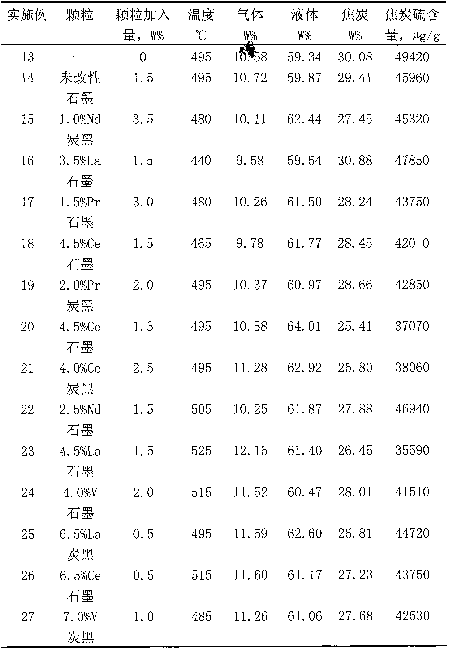
The invention provides a delayed coking method. The delayed coking method comprises the following steps: 1) moistening carbon particles through a moistening agent; dissolving or dispersing the moistened carbon particles into a dispersing agent with modifying substances dispersed; agitating the dispersing agent for 3 to 5 hours under normal temperature or the temperature of 50 to 80 DEG C; standing for 18 to 24 hours; drying for 2 to 4 hours under 120 to 150 DEG C; depositing metal elements in the modifying substances onto the carbon particles; and roasting for 3 to 5 hours under 450 to 560 DEG C through a muffle with the nitrogen protection, thus obtaining the modified carbon particles; 2) uniformly dispersing the modified carbon particles obtained in the step 1) into dispersing oil to obtain a modified carbon particle dispersing substance; and 3) adding the modified carbon particle dispersing substance obtained in the step 2) into the raw oil, and coking. By adopting the delayed coking method, the yield of liquid products can be increased, the yield of coke can be decreased, and the content of sulphur in coke can be decreased.

Description

technical field [0001] The invention relates to a delayed coking method, in particular to a delayed coking method in which additives are added to delayed coking raw materials. Background technique [0002] Hydrogenation and decarbonization are two different ways to lighten residual oil. Delayed coking is the most thorough thermal cracking process for decarbonization. Due to its mature technology, high conversion rate of residual oil, strong adaptability of raw materials and low production cost, while Widely used in residual oil deep processing. In recent years, as the supply of crude oil has become increasingly tight and the price difference between high-quality and low-quality crude oil has increased, domestic refining and chemical companies have processed a large amount of high-sulfur, high-asphaltene low-quality crude oil in order to improve economic efficiency. The vacuum residue of these crude oils is mainly produced through delayed coking. The degree of inferiority of...

Claims


Application Information

Patent Timeline
Patent Type & Authority Applications(China)
IPC IPC(8): C10G9/00
Inventor 齐文义黄新龙王永刚杨莹
Owner CHINA PETROCHEMICAL CORP
Why Eureka
Try Eureka