Composite coating equipment and manufacturing method for neodymium iron boron rare-earth permanent magnetic device

A rare earth permanent magnet and composite coating technology, which is used in inductor/transformer/magnet manufacturing, electrical components, sputtering coating, etc. Low efficiency and other problems, to achieve the effect of improving magnetic energy product and coercive force, improving corrosion resistance, and reducing the amount of rare earth

Inactive Publication Date: 2014-05-28
SHENYANG CHINANORTH VACUUM TECH CO LTD
View PDF9 Cites 21 Cited by
  • Summary
  • Abstract
  • Description
  • Claims
  • Application Information

AI Technical Summary

Problems solved by technology

[0005] The existing technology uses evaporation coating, the bonding force between the film layer and the substrate is poor, and there are deficiencies in improving the corrosion resistance of rare earth permanent magnet devices; there are also existing technologies that use magnetron sputtering coating, due to the low efficiency of magnetron sputtering, It is not suitable for low-cost mass production, and some have not solved the card installation technology, which is not easy to install, and the production is troublesome; some existing technologies use multi-arc ion coating, because there are large particles in the multi-arc ion coating, it cannot reach rare earth permanent magnet devices In order to solve the shortcomings of multi-arc ion plating, some people in the prior art thought of using multi-arc ion plating and magnetron sputtering composite coating, but none of them solved the problem of high efficiency, low cost, mass production technology , there are deficiencies in the equipment structure; especially the electroplating chemical treatment process of the rare earth permanent magnet device in the prior art, the energy consumption is high and there is pollution, requiring expensive water treatment equipment, improper treatment has a serious impact on the ecological environment, because the production process of the present invention The process is carried out in a vacuum, without using environmental pollutants, and will not pollute the ecological environment. At the same time, it also eliminates the influence of the "battery" effect on the reduction of magnetic properties in the electroplating process.

Method used


Image

  • Composite coating equipment and manufacturing method for neodymium iron boron rare-earth permanent magnetic device
  • Composite coating equipment and manufacturing method for neodymium iron boron rare-earth permanent magnetic device
  • Composite coating equipment and manufacturing method for neodymium iron boron rare-earth permanent magnetic device

Examples


Embodiment 1

[0046] Manufactured as follows:

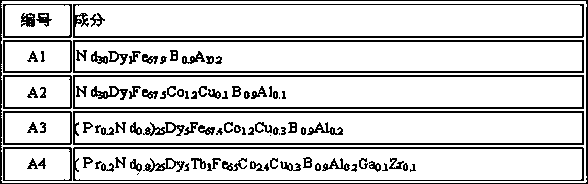
[0047] 1. Select 600Kg of alloys according to the composition of A1, A2, A3, and A4 in Table 1 for smelting. In the molten state, cast the alloy on a rotating copper roller with water cooling to cool to form alloy flakes, then carry out hydrogen crushing, and then carry out mixing after hydrogen crushing. After mixing the materials, jet milling is carried out, and then the materials are mixed with a mixer under the protection of nitrogen, and then sent to the nitrogen protection magnetic field orientation press for molding. The oxygen content in the protection box is 150ppm, the orientation magnetic field strength is 1.8T, and the temperature in the mold cavity is 2 ℃, the size of the magnetic block is 62×52×42mm, and the orientation direction is the 42-dimensional direction. After forming, it is packaged in a protective box, and then taken out for isostatic pressing. The isostatic pressing pressure is 200MPa, and then sent to the sintering equ...

Embodiment 2

[0058] Select the composition in embodiment 1 to make NdFeB rare earth permanent magnet device, the coating selects the first layer of Dy-Al alloy plating, the second layer of Al+Al plating, and the third layer of Al plating for temperature experiments, and the results are listed in Table 4 , No. 1 is the comparative example without heating or heat treatment during coating. It can be seen from Table 4 that the coating temperature and the heat treatment temperature after coating have an impact on the magnetic properties of the material, which significantly improves the coercive force of the magnet, that is, The use temperature of the magnet is increased, and at the same use temperature, the amount of heavy rare earths can be reduced, saving scarce resources.

[0059] Table 4. Effect of coating temperature and heat treatment temperature on magnetic properties and corrosion resistance

[0060]

[0061] Note: 1. Corrosion resistance (PCT test)

[0062] Experimental cond...


PUM

PropertyMeasurementUnit
thicknessaaaaaaaaaa
thicknessaaaaaaaaaa
thicknessaaaaaaaaaa

Abstract

The invention discloses composite coating equipment and a manufacturing method for a neodymium iron boron rare-earth permanent magnetic device. The coating equipment comprises a vacuum chamber, a cylindrical rotary cathode magnetron target, a planar cathode magnetron target, a cylindrical or rectangular cathode multi-arc ion target, an anode layer linear ion source, a rotating stand and a charging basket. When the coating equipment works, the rotating stand revolves in the vacuum chamber, and rotating shafts at two ends of the netlike charging basket are arranged on the rotating stand, namely that the rotating stand rotates automatically along with revolution. The cylindrical rotary cathode magnetron target is arranged in the rotating stand in the vacuum chamber; the planar magnetron target, the multi-arc ion target, the anode layer linear ion source and a heating device are arranged around the rotating stand in the vacuum chamber; a composite coating is divided into three layers, wherein the first layer is a magnetron sputtering coating of which the thickness is 0.1-5mu m, the second layer is a magnetron sputtering and multi-arc mixed coating of which the thickness is 1-15mu m, and the third layer is a magnetron sputtering coating of which the thickness is 0.1-5mu m. The composite coating is used for a surface treatment procedure of the rare-earth permanent magnetic device, so that the corrosion resistance of the rare-earth permanent magnetic device is improved, and the magnetic performance of the rare-earth permanent magnetic device is also improved.

Description

technical field [0001] The invention belongs to the field of permanent magnet devices, and in particular relates to a vacuum coating equipment and a manufacturing method for NdFeB rare earth permanent magnet devices. Background technique [0002] NdFeB rare earth permanent magnet materials, with their excellent magnetic properties, have been used more and more, and are widely used in medical nuclear magnetic resonance imaging, computer hard drives, audio, mobile phones, etc.; with the requirements of energy saving and low-carbon economy , NdFeB rare earth permanent magnet materials have begun to be used in auto parts, household appliances, energy saving and control motors, hybrid vehicles, wind power generation and other fields. [0003] The surface treatment process of rare earth permanent magnet devices in the prior art mainly includes electroplating Ni-Cu-Ni, electroplating Zn, electrophoresis, spraying and other technologies, and there is also a method of vacuum aluminum...

Claims


Application Information

Patent Timeline
Patent Type & Authority Applications(China)
IPC IPC(8): C23C14/35C23C14/06H01F41/02
Inventor 陈晓东孙宝玉
Owner SHENYANG CHINANORTH VACUUM TECH CO LTD
Why Eureka
Try Eureka