Atom gas cavity device with double reflectors and groove-shaped structure and manufacturing method thereof

A technology of atomic gas cavity and double mirror, applied in the direction of microstructure devices without moving elements, chemical instruments and methods, instruments using atomic clocks, etc., can solve the problems of low signal-to-noise ratio, difficulty, and cost of CPT signals, Achieve the effects of enhanced signal-to-noise ratio, improved stability, and easy implementation

Inactive Publication Date: 2014-07-23
CHINA ELECTRONIC TECH GRP CORP NO 38 RES INST
View PDF7 Cites 9 Cited by
  • Summary
  • Abstract
  • Description
  • Claims
  • Application Information

AI Technical Summary

Problems solved by technology

The optical path length of the interaction between light and atoms in the alkali metal atom gas cavity structure of this structure is limited by the thickness of the silicon wafer and the silicon processing technology, usually 1 mm to 2 mm, and it is difficult and expensive to further increase the thickness, thus limiting the interaction between light and atoms. The action optical path, the signal-to-noise ratio of the CPT signal is low, which affects the frequency stability of the CPT atomic clock

Method used


Image

  • Atom gas cavity device with double reflectors and groove-shaped structure and manufacturing method thereof
  • Atom gas cavity device with double reflectors and groove-shaped structure and manufacturing method thereof
  • Atom gas cavity device with double reflectors and groove-shaped structure and manufacturing method thereof

Examples


Embodiment 1

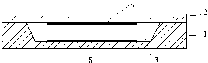
[0030] see figure 1 and figure 2 , an atomic gas cavity device with double mirrors and a groove-shaped structure includes a silicon wafer 1 and a glass wafer 2 . One side of the silicon chip 1 is provided with a groove, the cross section of the groove is an inverted trapezoid, and the inner bottom of the groove is provided with a lower reflector 5; one side of the glass sheet 2 is provided with an upper reflector 4; the silicon chip 1 and the glass sheet 2 The atomic gas cavity is formed by bonding 3 The device, the upper mirror 4 on the glass sheet 2 is correspondingly located in the groove of the silicon wafer 1, and corresponds to the lower mirror 5.

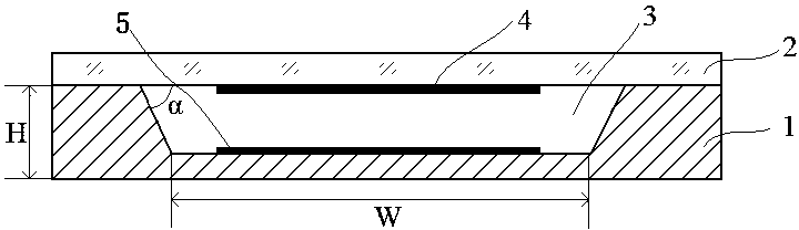
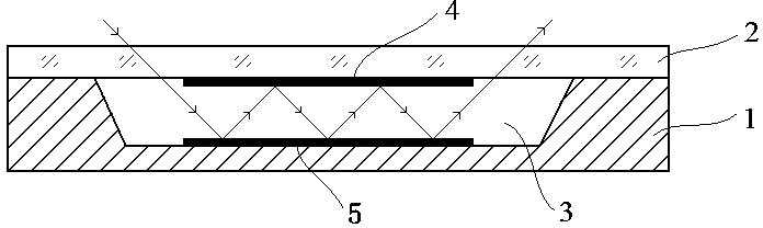
[0031] like image 3 As shown, the optical path of the laser in the atomic gas cavity 3 device is mainly determined by the width W of the bottom of the groove, and the optical path can be changed by adjusting the size of W. see Figure 4 , in the traditional atomic gas cavity device, the laser is directly injected from t...

Embodiment 2

[0039] The structure of the atomic gas cavity of the present embodiment is as follows figure 1 As shown, the specific implementation scheme is as follows:

[0040] 1. Select a P(100) silicon wafer 1 with a thickness of 0.5-1 mm, use silicon nitride as a mask, and perform anisotropic wet etching through TMAH solution to form an inverted trapezoidal cross section on the silicon wafer 1. One hundred and fifty grooves, the side walls of the grooves are {111} crystal planes, and the lateral width of the through holes is 5 mm. The corrosion temperature of TMAH solution is 80°C;

[0041] 2. Using the sputtering process and hard mask technology, one hundred and fifty metal film mirrors, namely the upper mirror 4, are fabricated on one side of the glass sheet 2; at the bottom of each groove of the silicon wafer 1 Make one hundred and fifty metal film reflectors, that is, the lower reflector 5;

[0042] 3. Carry out silicon-glass bonding, and feed cesium vapor and buffer gas at the s...


PUM

PropertyMeasurementUnit
angleaaaaaaaaaa
widthaaaaaaaaaa
thicknessaaaaaaaaaa

Abstract

The invention relates to an atom gas cavity device with double reflectors and a groove-shaped structure and a manufacturing method of the atom gas cavity device. The atom gas cavity device is composed of a cavity body structure defined by a silicon wafer and a glass sheet in a bonding mode, wherein the bottom of the silicon wafer is provided with one reflector, the silicon wafer is provided with a groove, and the other reflector is arranged inside the glass sheet. The cross section of the groove is of an inversed trapezoidal shape structure, and is formed by a 100-type monocrystalline silicon wafer in a silicon anisotropic wet etching mode. The side walls of the groove are 111-type crystal faces of the silicon wafer. The interior of the glass sheet and the bottom of the groove of the silicon wafer are respectively provided with one reflector, and the reflectors are used for reflecting laser many times. The atom gas cavity device can be used for atomic clocks, magnetometers and other systems, laser is reflected many times between the double reflectors, the space length of interaction between laser and atom gas is increased, the signal-to-noise ratio of coherent population trapping signals is increased, and system stability can be improved.

Description

technical field [0001] The invention belongs to the technical field of micro-electro-mechanical system (MEMS) device manufacturing and packaging, and the technical field of atomic physics devices, and specifically relates to a micro-atomic cavity structure based on MEMS technology and a manufacturing method thereof. Background technique [0002] Atomic clocks can measure time with an accuracy of one billionth of a second or even higher. Atomic clocks are currently the most accurate artificial clocks, and their related research is of great significance. CPT (Coherent Population Trapping, coherent layout trapping effect) atomic clock is an atomic clock frequency source realized by using two-color coherent light to interact with atoms to prepare atoms into a coherent state, and using the CPT signal as a microwave frequency discrimination signal. Due to the characteristics of easy miniaturization, low power consumption and high frequency stability, the CPT atomic clock has been ...

Claims


Application Information

Patent Timeline
Patent Type & Authority Applications(China)
IPC IPC(8): G04F5/14B81B1/00B81C1/00B81C3/00
Inventor 许磊王光池郑林华刘建勇
Owner CHINA ELECTRONIC TECH GRP CORP NO 38 RES INST
Why Eureka
Try Eureka