
Cadmium Telluride Solar Cells with Tellurium Molybdenum Multilayer Composite Thin Films

A multi-layer composite and solar cell technology, which is applied in the direction of circuits, photovoltaic power generation, electrical components, etc., can solve problems such as negative impact on device stability

Inactive Publication Date: 2017-01-11
SICHUAN UNIV
View PDF3 Cites 0 Cited by
  • Summary
  • Abstract
  • Description
  • Claims
  • Application Information

AI Technical Summary

Problems solved by technology

In the long run, it will have a negative impact on device stability

Method used

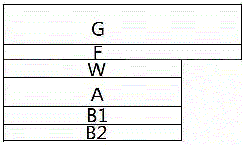
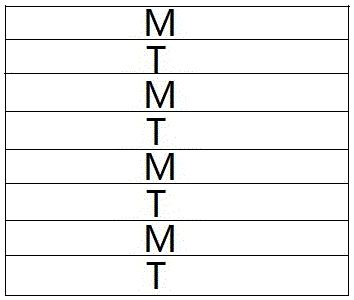
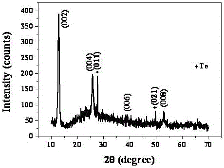

Image

  • Cadmium Telluride Solar Cells with Tellurium Molybdenum Multilayer Composite Thin Films
  • Cadmium Telluride Solar Cells with Tellurium Molybdenum Multilayer Composite Thin Films
  • Cadmium Telluride Solar Cells with Tellurium Molybdenum Multilayer Composite Thin Films

Examples


Embodiment 1

[0017] (1) Preparation of tellurium-molybdenum multilayer composite film

[0018] Put the sample into the vacuum chamber with a vacuum of 10 -4 pa, the sample temperature is room temperature, and the electron beam evaporation method is used to alternately evaporate tellurium and molybdenum, wherein the purity of tellurium is 99.99% and above, and the purity of molybdenum is 99.99% and above. The thickness of deposited tellurium is 1~10nm, the thickness ratio of tellurium and molybdenum is 3.4, and the total thickness of tellurium-molybdenum multilayer composite film is 250 nm;

[0019] (2) Post-processing tellurium molybdenum multilayer composite film

[0020] Take out the sample deposited with tellurium-molybdenum multilayer composite film, put it into a vacuum annealing furnace protected by nitrogen gas, and carry out post-treatment at a temperature of 300 0 C~400 0 C, the time is 10-60 minutes, and then naturally cooled to room temperature, that is, a sample with a thin ...

Embodiment 2

[0022] (1) Install the target and sample

[0023] Fix the tellurium target (purity 99.99% and above) and the molybdenum target (purity 99.99% and above) respectively on the two target positions corresponding to the sputtering device, fix the sample on the substrate position, and adjust the distance between the target and the substrate. The distance is 6~9 cm;

[0024] (2) Preparation of tellurium molybdenum multilayer composite film

[0025] Tellurium and molybdenum were sputtered alternately and sequentially at room temperature to obtain tellurium-molybdenum multilayer composite films, in which the background vacuum was ~10 -4 Pa, the working gas is argon, the working pressure is 0.1~3.5 Pa, the sputtering power of tellurium target is 30~100 W, the sputtering power of molybdenum target is 30~300 W, the thickness of tellurium is 1~10 nm, and the thickness ratio of tellurium and molybdenum is 3 , the total sputtering thickness is 100 nm;

[0026] (3) Post-treatment tellurium...


PUM

PropertyMeasurementUnit
thicknessaaaaaaaaaa

Abstract

The invention discloses a cadmium telluride solar battery provided with a tellurium-molybdenum multilayer composite thin film and belongs to the field of new energy materials and devices. According to the solar battery, the tellurium-molybdenum multilayer composite thin film is adopted as a copper-free transition layer of the cadmium telluride solar battery. On one hand, due to the fact that the transition layer has the precipitated phase of tellurium, there is no need to obtain a tellurium-enriched layer through a wet process after cadmium telluride is annealed; even if a dry process is adopted, independent deposition of a tellurium layer is not needed. On the other hand, the transition layer has the principal phase of molybdenum telluride and serves as a p-type semiconductor, and the discontinuity between the transition layer and a cadmium telluride valence band is little, so the transition layer can play a good transition role, and ohmic contact between the cadmium telluride and a metal electrode is achieved. By the adoption of the structure, the solar battery avoids chemical corrosion and achieves low-resistance contact, the performance of the solar battery can be effectively improved, and the long-term stability of a device is improved.

Description

technical field [0001] The invention belongs to the field of new energy materials and devices, and in particular relates to a preparation method of a cadmium telluride thin film solar cell. Background technique [0002] Using semiconductor technology to directly convert solar energy into electrical energy and realize solar photovoltaic power generation will play a vital role in alleviating the depletion of fossil energy and reducing greenhouse gas emissions. For more than a decade, some major countries in the world have been actively developing compound thin-film solar cells, such as copper indium selenium solar cells, cadmium telluride solar cells, and new dye-sensitized solar cells. On the one hand, the adoption of thin-film technology effectively reduces production costs; on the other hand, the improvement of its photoelectric conversion efficiency also reduces production costs. These compound thin-film solar cells, especially the research and development of cadmium tell...

Claims


Application Information

Patent Timeline
Patent Type & Authority Patents(China)
IPC IPC(8): H01L31/073H01L31/0224
CPCY02E10/543
Inventor 李卫王洲玲张静全冯良桓武莉莉黎兵曾广根王文武胡玉唐容喆
Owner SICHUAN UNIV
Learn More