Composite nanometer filter material with catalytic function as well as preparation method and application of composite nanometer filter material

A composite and nanofiltration technology, applied in chemical instruments and methods, separation methods, physical/chemical process catalysts, etc., can solve the problem of small contact area between catalyst and gas, low porosity of fibrous layer, lack of catalytic effect, etc. problems, to achieve good application prospects, high removal efficiency, and long service life

Active Publication Date: 2014-12-24
ZHEJIANG UNIV
View PDF7 Cites 15 Cited by
  • Summary
  • Abstract
  • Description
  • Claims
  • Application Information

AI Technical Summary

Problems solved by technology
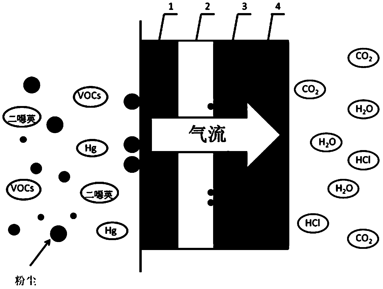
The scheme disclosed in this patent document is to first mix the catalyst and polytetrafluoroethylene resin and add liquid paraffin to make a film, and then use a fiber opener to split the film loaded with the catalyst into a fibrous layer with a network structure. The reason is that the porosity of the fibrous layer is low, and part of the catalyst is coated in the polytetrafluoroethylene resin, which cannot play a catalytic role, and the contact area between the catalyst and the gas is small.
In the technology disclosed in this patent document, the preparation of the catalytic layer is mainly to adsorb the catalyst on the surface of polyphenylene sulfide (PPS) by impregnation method. Although the contact area between the catalyst and the gas is increased, the catalyst is easy to fall off.
[0007] On the other hand, studies have shown that when the particle size is between 0.1 and 0.5 μm, it is difficult to be captured by ordinary bag filter through electrostatic precipitator or inertial collision and interception because the particle size is too small. The material cannot block particles of this size due to the large voids

Method used


Image

  • Composite nanometer filter material with catalytic function as well as preparation method and application of composite nanometer filter material
  • Composite nanometer filter material with catalytic function as well as preparation method and application of composite nanometer filter material
  • Composite nanometer filter material with catalytic function as well as preparation method and application of composite nanometer filter material

Examples


Embodiment 1

[0041] Preparation of catalytic filter layer

[0042] (1) Preparation of nanofibers by electrospinning

[0043] Take PVP (molar mass 45,000-55,000g / mol) and add it to absolute ethanol, stir magnetically for 30 minutes until PVP is completely dissolved, add tetrabutyl titanate and glacial acetic acid to make a Ti precursor solution, and stir magnetically at room temperature for 18 hours to obtain the precursor Precursor solution; take 9mL precursor solution with a plastic syringe, fix it at a position 15cm away from the center of the drum, and wrap aluminum foil on the drum as a receiving device for nanofibers; apply a high voltage power supply of 15kV to the stainless steel needle, rotate the drum at 50r / min, and inject the syringe at a speed of 1mL / min, get TiO 2 Nanofibers;

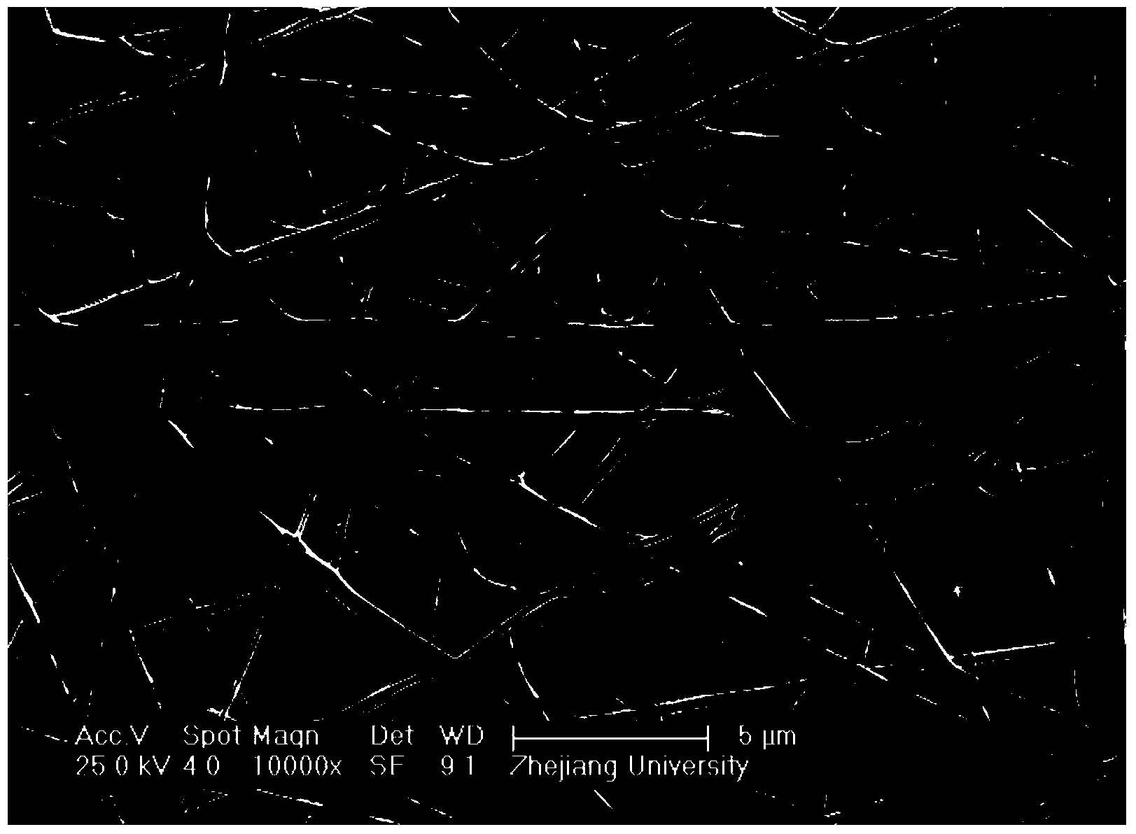
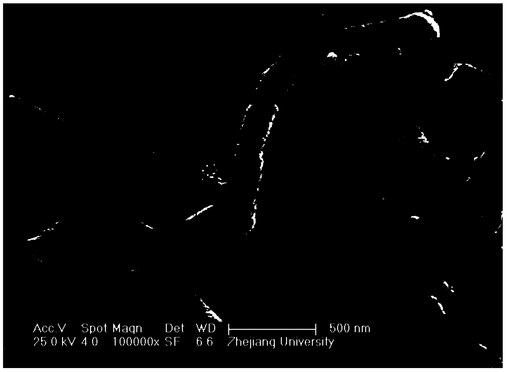
[0044] (2) Calcination to form nanofiber carrier

[0045] After spinning, remove the aluminum foil and place it at room temperature for 12 hours to fully hydrolyze the nanofibers; put the placed alum...

Embodiment 2

[0049] Preparation of catalytic filter layer

[0050] (1) Preparation of nanofibers by electrospinning

[0051] Take PVP (molar mass 45000-55000g / mol) and add it to absolute ethanol, stir magnetically for 30 minutes until PVP is completely dissolved, add tetrabutyl titanate, ethyl orthosilicate and glacial acetic acid to make Si / Ti molar ratio 1 : 9 precursor solution, magnetically stirred for 18h at room temperature; 9mL precursor solution was taken with a plastic syringe, fixed at a position 15cm away from the center of the drum, and aluminum foil was wrapped on the drum as a receiving device for nanofibers; a high voltage power supply of 15kV was added at the stainless steel needle, The rotating speed of the drum is 50r / min, the perfusion speed of the syringe is 1mL / min, SiO 2 -TiO 2 Composite nanofibers;

[0052] (2) Calcination to form nanofiber carrier

[0053] After spinning, remove the aluminum foil and place it at room temperature for 12 hours to fully hydrolyze t...

Embodiment 3

[0057] Preparation of catalytic filter layer

[0058] (1) Preparation of nanofibers by electrospinning

[0059] Take PVP (molar mass 45000-55000g / mol) and add it to absolute ethanol, stir magnetically for 30 minutes until PVP is completely dissolved, add tetrabutyl titanate, ethyl orthosilicate and glacial acetic acid to make Si / Ti molar ratio 1 :4 precursor solution, magnetically stirred at room temperature for 18h; 9mL precursor solution was taken with a plastic syringe, fixed at a position 15cm away from the center of the drum, and aluminum foil was wrapped on the drum as a receiving device for nanofibers; The rotating speed of the drum is 50r / min, the perfusion speed of the syringe is 1mL / min, SiO 2 -TiO 2 Composite nanofibers;

[0060] (2) Calcination to form nanofiber carrier

[0061] After spinning, remove the aluminum foil and place it at room temperature for 12 hours to fully hydrolyze the nanofibers; put the placed aluminum foil in a crucible and put it into a mu...


PUM

PropertyMeasurementUnit
diameteraaaaaaaaaa
diameteraaaaaaaaaa
diameteraaaaaaaaaa

Abstract

The invention discloses a composite nanometer filter material with a catalytic function. The composite nanometer filter material comprises a dust facing layer, a buffer layer, a catalytic filter layer and a supporting layer which are sequentially coincided, wherein each layer contains fibers crosslinked into a mesh; the fiber diameters of the dust facing layer and the supporting layer are larger than 3mu m; the fiber diameter of the buffer layer is 1-3mu m; the fiber diameter of the catalytic filter layer is small than 1mu m; the total gram weight of the dust facing layer, the buffer layer and the supporting layer is respectively 25-500grams per square meter; the total gram weight of the catalytic filter layer is 10-250grams per square meter; and the catalytic filter layer comprises a nanometer fiber carrier and active ingredients loaded on the nanometer fiber carrier. The nanometer filter material disclosed by the invention is high in removal efficiency and long in service life. The invention also discloses a method for preparing the composite nanometer filter material with the catalytic function. The catalytic active ingredients are introduced in situ, so that the problems that the bonding property of the catalyst and the fiber filter material in the catalytic filter material is low, the catalyst particles are easy to drop and the like are solved.

Description

technical field [0001] The invention relates to the technical field of tail gas treatment, in particular to a composite nano filter material with catalytic function and its preparation method and application. Background technique [0002] my country is a big energy consumption country, the primary energy consumption structure is dominated by coal, and the SO produced by coal combustion 2 , NO x Pollutants such as mercury, volatile organic compounds (VOCs) and dioxins make my country one of the countries with the most serious air pollution in the world. In order to improve the air pollution situation, the Ministry of Environmental Protection promulgated and implemented the new "Emission Standards of Air Pollutants for Thermal Power Plants" (GB13223-2011), setting the world's most stringent pollutant emission limits and for the first time stipulating mercury emission limits Value (0.03mg / m 3 ). In 2010, the General Office of the State Council officially proposed the preven...

Claims


Application Information

Patent Timeline
Patent Type & Authority Applications(China)
IPC IPC(8): B01D39/14B01J35/02B32B5/14B01D46/02B01D53/86
Inventor 高翔陈景欢骆仲泱岑可法倪明江于馨凝郑成航吴卫红施正伦周劲松方梦祥余春江王树荣程乐鸣王勤辉
Owner ZHEJIANG UNIV
Why Eureka
Try Eureka