Dual Optical Frequency Comb Optical Imaging Method Based on Continuous Frequency Stabilized Laser

A dual optical frequency comb and optical frequency comb technology, which is applied in spectrum investigation and other directions, can solve problems such as complex detection and control processes, achieve stable output laser characteristics, fast and high acquisition, and enhance compactness and applicability

Active Publication Date: 2016-06-01
CHONGQING HUAPU INFORMATION TECH CO LTD
View PDF11 Cites 0 Cited by
  • Summary
  • Abstract
  • Description
  • Claims
  • Application Information

AI Technical Summary

Problems solved by technology

However, the detection and control process of the phase drift frequency of the optical comb carrier envelope due to the difference between the group velocity and the phase velocity during the pulse propagation process is relatively complicated. Usually, it is necessary to perform power amplification and spectral broadening on the output light of the optical comb, and then use a common linear or non-collinear f-2f Perform optical frequency doubling and optical beam combining beat frequency from the reference optical system, and extract the carrier envelope phase drift frequency
In the above-mentioned process, not only the dispersion characteristics and polarization state of the pulse need to be well controlled, but also the temperature of the nonlinear crystal, the phase matching degree of the entire optical system, and the adjustment accuracy and stability of the optical path all have higher requirements. Requirements, these will undoubtedly have a negative impact on the application and promotion of optical frequency comb technology

Method used


Image

  • Dual Optical Frequency Comb Optical Imaging Method Based on Continuous Frequency Stabilized Laser
  • Dual Optical Frequency Comb Optical Imaging Method Based on Continuous Frequency Stabilized Laser
  • Dual Optical Frequency Comb Optical Imaging Method Based on Continuous Frequency Stabilized Laser

Examples


Embodiment 1

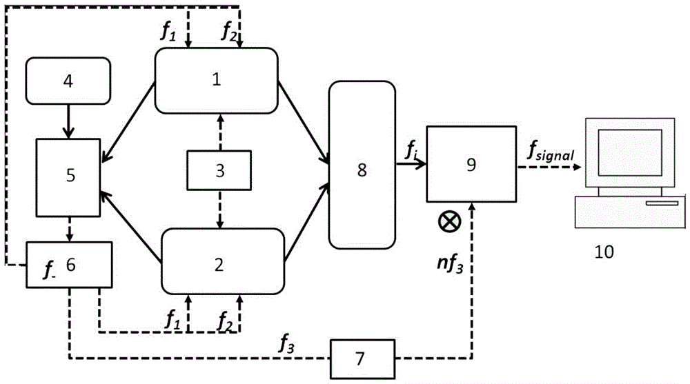
[0029] Embodiment one: if figure 1 As shown, this embodiment specifically relates to a dual optical frequency comb optical imaging method based on a continuous frequency-stabilized laser, in which the dual optical comb seed source (ie optical frequency comb seed source 1 and optical frequency comb seed source 2) is controlled by repetition frequency Module 3 is locked on an external stable atomic clock. At the same time, continuous frequency-stabilized laser and dual optical comb interaction module 5 combines the continuous laser generated by continuous frequency-stabilized laser generation module 4 with two optical frequency comb seed sources (that is, optical frequency comb seed The output laser of source 1 and optical frequency comb seed source 2) is used for beat frequency, and the electrical signal carrying the frequency instability of the optical comb is extracted, and the signal is subjected to RF signal power distribution and processing, and a part of it is directly us...

Embodiment 2

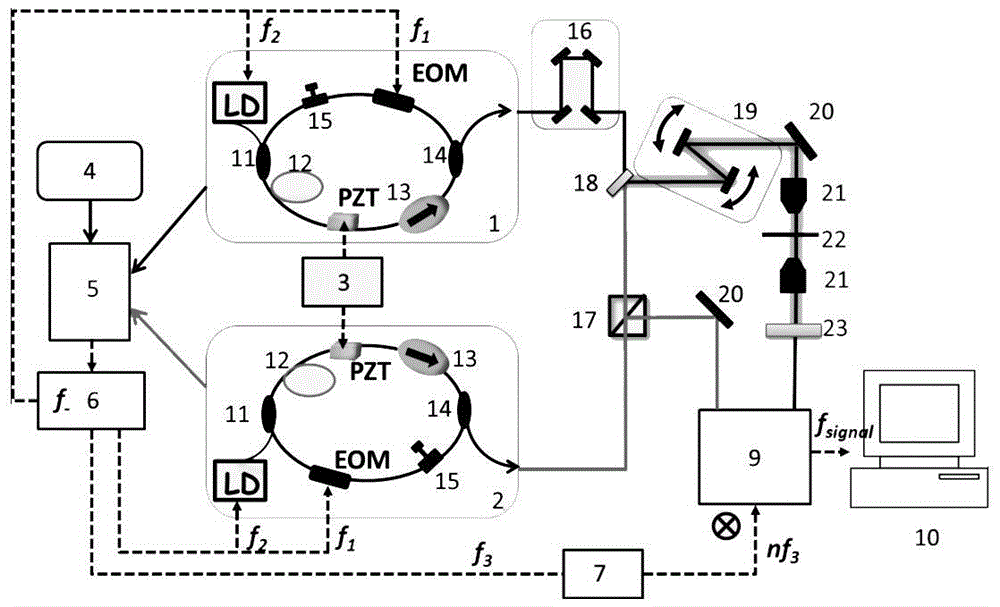
[0046] Embodiment two: if figure 2 Shown is a schematic diagram of dual-comb sample scanning imaging using a polarization rotation-locked mode all-fiber laser as an optical frequency comb seed source. The specific steps are as follows:

[0047] (1) The two optical frequency comb seed sources 1 and 2 both adopt an all-fiber structure, use a 980nm semiconductor laser LD as a pump source, enter the laser cavity through a fiber wavelength division multiplexer 11, and single-mode ytterbium-doped The gain fiber 12 is used as the gain medium, the fiber isolator 13 ensures the one-way operation of the laser, the piezoelectric ceramic crystal PZT is wound on the single-mode fiber in the cavity, and the electro-optic modulator EOM adopts a fiber-optic phase and intensity modulator; The polarization controller 15 makes the laser reach a stable mode-locked state; the mode-locked pulse laser is output through the fiber coupler 14 .

[0048] (2) In the repetition frequency locking module ...

Embodiment 3

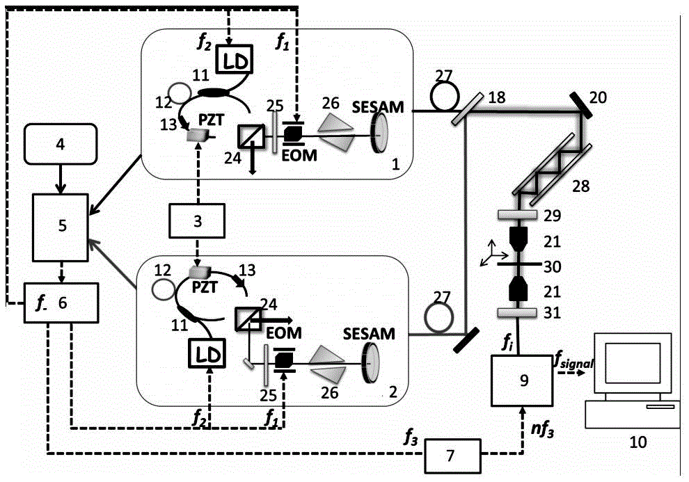
[0056] Embodiment three: as image 3 Shown is a SESAM-based half-space half-fiber laser as an optical frequency comb seed source for dual-comb coherent anti-Stokes Raman scattering imaging. The specific steps are as follows:

[0057] (1) The two optical frequency comb seed sources 1 and 2 both adopt an all-fiber structure, use a 980nm semiconductor laser LD as a pump source, enter the laser cavity through a fiber wavelength division multiplexer 11, and use a gain fiber 12 as a gain medium, the fiber isolator 13 ensures the one-way operation of the laser, and the piezoelectric ceramic crystal PZT is wound on the single-mode fiber in the cavity.

[0058] (2) Based on the half-space and half-fiber characteristics of the laser resonator, the intracavity polarization beam splitter 24 is used in conjunction with the intracavity half-wave plate 25, so that part of the laser output from the polarization beam splitter 24 is used as the optical frequency comb seed source 1, 2, the othe...


PUM


Abstract

The invention discloses a double-optical frequency comb optical imaging method based on a continuous frequency stabilized laser. According to the optical imaging method, two optical frequency comb seed resources are locked onto a stable outside atomic clock through a repetition frequency control module, meanwhile, an electric signal which has optical comb frequency instability is extracted through interaction between the continuous frequency stabilized laser and the laser output by the two optical frequency comb seed resources, radio-frequency signal power distribution and processing are conducted on the electric signal, a part of the electric signal is directly used for feedback control of the laser resonator character of the two optical frequency comb seed resources so as to stabilize the output carrier envelope phase frequency of a semiconductor laser unit, the other part of the electric signal is used for being mixed with a periodical interference spectrum signal generated by a double-optical comb imaging system so as to further counteract the frequency variations of the optical comb system, and therefore the measurement precision of the whole double-optical comb imaging system is controlled from two aspects and quick and super-high-resolution optical comb coherent imaging is achieved.

Description

technical field [0001] The invention belongs to the technical field of ultrafast lasers, in particular to a dual optical frequency comb optical imaging method based on continuous frequency-stabilized lasers. Background technique [0002] The development of optical microscopic imaging technology has a long history, and it has been continuously improved along with the deepening of human exploration of the microcosm. As early as the first century BC, people discovered that water droplets could be used to observe the magnified image of an object. The spatial resolution of traditional optical imaging systems is limited by the diffraction limit. Generally speaking, the spatial resolution limited by the diffraction limit of optical imaging systems is about half of the wavelength of the probe light. For object details smaller than this imaging limit, traditional optical systems will powerless. In the 1980s, the emergence of non-optical scanning probe microscopy, especially atomic ...

Claims


Application Information

Patent Timeline
Patent Type & Authority Patents(China)
IPC IPC(8): G01J3/28
Inventor 白东碧李文雪曾和平
Owner CHONGQING HUAPU INFORMATION TECH CO LTD
Why Eureka
Try Eureka