Thick film pyroelectric sensitive element and preparation method thereof

A sensitive element and pyroelectric technology, which is applied in the manufacture/processing of thermoelectric devices, the lead-out material of thermoelectric device junctions, and electrical radiation detectors. The problem of high production cost is to achieve the effect of being sensitive to weak environmental temperature changes, conducive to industrial production, and easy to batch process.

Inactive Publication Date: 2015-06-17
UNIV OF ELECTRONIC SCI & TECH OF CHINA
View PDF6 Cites 15 Cited by
  • Summary
  • Abstract
  • Description
  • Claims
  • Application Information

AI Technical Summary

Problems solved by technology

The first single crystal forms such as triglyceride sulfate (TGS) and lithium tantalate (LiTaO 3 ) etc. have high pyroelectric coefficients and high sensitivity, but the cost of single crystal materials is high and the manufacturing process is difficult
The second type is ceramic blocks prepared by thinning technology, such as barium strontium titanate (BST), etc. Although ceramic devices have good pyroelectric performance, ceramic sensitive components not only have high requirements for thinning technology, but also because ceramics Sensitive components have large heat capacity, which leads to a significant decrease in device performance, especially high-frequency performance
The third type of ceramic film type, such as lead zirconate titanate (PZT) and lead lanthanum titanate (PLT), reduces the heat capacity of the device through the use of thin film technology, and has the characteristics of excellent performance and fast response speed. However, the film deposition conditions and

Method used


Image

  • Thick film pyroelectric sensitive element and preparation method thereof
  • Thick film pyroelectric sensitive element and preparation method thereof
  • Thick film pyroelectric sensitive element and preparation method thereof

Examples


Embodiment Construction

[0031] The technical solutions, structural features and realization effects of the present invention will be further described in detail below through specific implementation methods and accompanying drawings.

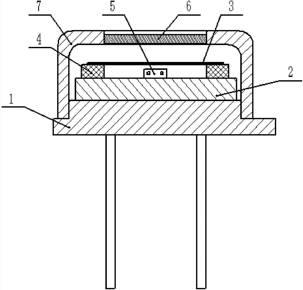
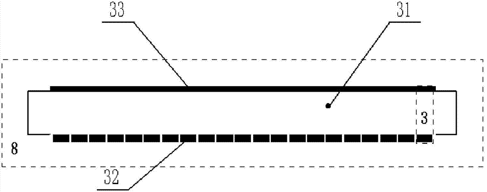
[0032] The preparation process steps of the pyroelectric infrared sensitive element 3 of the present invention include:

[0033] 1. Preparation of the heat-sensitive layer 31 .

[0034] 1) Mix BST and PVDF into N,N-dimethylformamide (DMF) at a mass ratio of 1:1, wherein, PVDF:DMF=1:7, and ultrasonically stir until a uniformly mixed slurry is obtained;

[0035] 2) Spray the slurry prepared in step 1) on a flat glass substrate by spraying method, and then let it stand for 10 minutes. After the slurry is leveled, put it into an oven at 80°C. After drying to form a thick film, remove it from the glass substrate peeled off and fixed in a plane fixture, the two surfaces of the fixture are made of glass or metal foil with good flatness and thermal stability, and then kept in...


PUM

PropertyMeasurementUnit
Thicknessaaaaaaaaaa

Abstract

The invention belongs to the technical field of electronic materials and components, and particularly relates to a thick film pyroelectric sensitive element and a preparation method thereof. The thick film pyroelectric infrared sensitive element comprises a top electrode, a heat sensitive layer and a bottom electrode. The top electrode is used as a common electrode, and the thickness of the infrared radiation absorbing surface of the top electrode is 10-500 nm. The heat sensitive layer is arranged between the top electrode and the bottom electrode and is prepared by compounding pyroelectric ceramic powder and organic pyroelectric polymers, and the thickness of the heat sensitive layer is 1-100 um. The bottom electrode is used for leading out pyroelectric response signals, and the thickness of the bottom electrode is 10 nm to 1 um. According to different types of pyroelectric infrared sensitive element, the top electrode and the bottom electrode of the infrared sensitive element are imaged. The thick film pyroelectric sensitive element is applied to safety burglary prevention, human body detection and the like in the civilian field. The thick film pyroelectric sensitive element has the advantages of being good in thermal insulation effect, more sensitive to weak environment temperature change, higher in sensitivity, simple in manufacturing technology, low in cost, capable of facilitating batch processing and beneficial to industrialization production.

Description

technical field [0001] The invention belongs to the technical field of electronic materials and components, and more specifically relates to a pyroelectric infrared sensitive component and a preparation method thereof. Background technique [0002] Pyroelectric infrared detector is a heat-sensitive detector designed according to pyroelectric effect, which converts infrared radiation signal into electrical signal, because it works at room temperature without refrigeration, low power consumption, light weight, and wide spectral response range , easy imaging, and high cost performance have become one of the current research hotspots in the field of infrared detection technology. As the core component of infrared detection technology, pyroelectric infrared detectors have been widely used in various security and anti-theft, human detection, etc. in the civilian field, various thermal sights, guided missiles, etc. Heat leakage and corrosion, and even disease diagnosis in the medi...

Claims


Application Information

Patent Timeline
IPC IPC(8): H01L35/34H01L35/14G01J5/12
Inventor 罗文博孟佳吴传贵帅垚吴勤勤俞玉澄张万里
Owner UNIV OF ELECTRONIC SCI & TECH OF CHINA
Why Eureka
Try Eureka