swsr‑6 Sulfur recovery process and device

A sulfur recovery and process technology, which is applied in the preparation/purification of sulfur, the preparation of alkali metal sulfites, etc., can solve the problems that the sulfur recovery effect cannot meet the environmental protection requirements, the high requirements for device safety control, and the high energy consumption of the device, and achieves The effect of saving land, convenient operation and reducing load

Active Publication Date: 2017-10-13
SHANDONG SUNWAY PETROCHEMICAL ENGINEERING CO LTD
View PDF4 Cites 1 Cited by
  • Summary
  • Abstract
  • Description
  • Claims
  • Application Information

AI Technical Summary

Problems solved by technology

[0004] The process is long, and the safety control requirements of the device are high; the regeneration of the alcohol amine solution consumes a large amount of steam, the energy consumption of the device is high, the operation is uneconomical, and the sulfur recovery effect cannot meet the needs of further improvement of environmental protection requirements

Method used


Image

  • swsr‑6 Sulfur recovery process and device

Examples


Embodiment 1

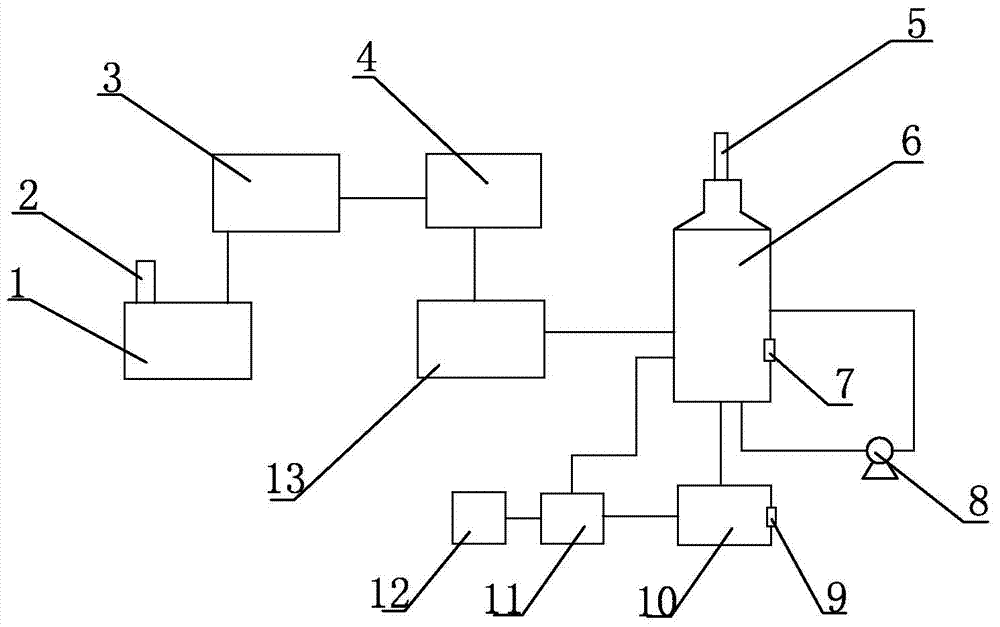
[0065] A SWSR-6 sulfur recovery device, comprising a sulfur production combustion furnace 1, a Claus reaction system 3, a tail gas incineration system 13 and a flue gas purification tower 6 connected in sequence through pipelines, and the sulfur production combustion furnace 1 is equipped with a hydrogen sulfide-containing Acid gas inlet 2, the top of the flue gas purification tower 6 is provided with a purified flue gas outlet 5, the outlet at the bottom of the flue gas purification tower 6 is connected to the inlet of the side of the flue gas purification tower 6 through a pipeline, and the pipeline is provided with a circulation pump 8 at the bottom of the purification tower, One side of the flue gas purification tower 6 is also provided with a first sodium hydroxide inlet 7, and the bottom of the flue gas purification tower 6 is connected to a neutralization tank 10 through a pipeline, and a second sodium hydroxide inlet 9 is arranged on the neutralization tank 10, and the n...

Embodiment 2

[0080] The SWSR-6 sulfur recovery process used in Example 2 and the SWSR-6 sulfur recovery device are the same as in Example 1, the only difference being that step ④ in the SWSR-6 sulfur recovery process is the liquid evaporated in the equilibrium absorption process, and the smoke In the gas purification tower 6, process water needs to be supplemented to keep the liquid phase liquid level in the flue gas purification tower at 80%; add sodium hydroxide to the flue gas purification tower 6 through the first sodium hydroxide inlet 7, so that the flue gas purification tower The pH value in 6 is controlled at 7, and sodium hydroxide is added to the neutralization tank 10 through the second sodium hydroxide inlet 9, and the pH value in the neutralization tank 10 is controlled at 8.

[0081] Example 2 The sulfur production process produces sulfur products that meet the requirements of GB / T2449, and the desulfurization process produces anhydrous sodium sulfite products that meet GB1894...


PUM


Abstract

The invention relates to a process and device for sulfur recovery and tail gas treatment, in particular to a SWSR-6 sulfur recovery process; acidic gas containing hydrogen sulfide undergoes Claus reaction to generate sulfur and sulfur production tail gas, wherein sulfur is recovered and sulfur production tail gas Incineration, all sulfur-containing media are converted into SO2, forming SO2-containing flue gas, SO2-containing flue gas contacts with absorbent in the flue gas purification tower, SO2 in the flue gas is absorbed by the absorbent, and the flue gas generated in the flue gas purification tower The salt solution reacts with lye, and after crystallization and centrifugation, sodium sulfite is obtained, and the purified flue gas is discharged after removing SO2. The desulfurization process of the present invention produces anhydrous sodium sulfite products that comply with GB 1894, the sulfur recovery rate of the device is close to 100%, and the desulfurization efficiency is close to 100%, ensuring that the SO2 concentration in the exhaust gas of the sulfur recovery device is less than 50mg/Nm3. The present invention also provides SWSR‑6 sulfur recovery device.

Description

technical field [0001] The invention relates to a process and device for sulfur recovery and tail gas treatment, in particular to a SWSR-6 sulfur recovery process and device. Background technique [0002] my country has been advocating energy conservation and emission reduction work, strictly controlling the emission of sulfur dioxide in the atmosphere. Before 2012, the emission concentration of sulfur dioxide stipulated by the national standard was no higher than 960mg / Nm 3 . According to the GB31570-2015 "Petroleum Refining Industry Pollutant Discharge Standard" implemented on July 1, 2015, sulfur recovery unit SO 2 The emission limit is 400mg / Nm 3 , specific region SO 2 The emission limit is 100mg / Nm 3 . Sinopec actively implements the green and low-carbon development strategy, and regards the reduction of sulfur dioxide emission concentration in flue gas from sulfur plants as one of the important indicators for the refining sector to strive for world-class status. I...

Claims


Application Information

Patent Timeline
Patent Type & Authority Patents(China)
IPC IPC(8): C01B17/04C01D5/14
Inventor 王震宇高炬张恒拓
Owner SHANDONG SUNWAY PETROCHEMICAL ENGINEERING CO LTD
Why Eureka
Try Eureka