Process for synergic removal of flue gas pollutants through complexing absorption synchronous electrolytic reduction

A technology of complex absorption and pollutants, which is applied in external electrostatic separators, dispersed particle separation, chemical instruments and methods, etc., can solve the problems of wasting power consumption, reducing reaction conversion rate, and increasing impeller wear, and achieves simplified structure, The effect of improving conversion rate and reducing energy consumption

Inactive Publication Date: 2016-02-03
WUHAN UNIV OF SCI & TECH +1
View PDF4 Cites 4 Cited by
  • Summary
  • Abstract
  • Description
  • Claims
  • Application Information

AI Technical Summary

Problems solved by technology

[0004] On the one hand, there are following problems in adopting the iron filings method in the regeneration step: (1) Since the absorption liquid is acidic, the iron filings are easily corroded, resulting in a large consumption of iron filings, and the concentration of iron ions in the absorption liquid is too high, which increases the efficiency of iron removal. The cost also affects the quality of desulfurization and denitrification by-products; (2) Since the elemental iron in the iron filings is oxidized and corroded into the solution, the pH value of the absorption solution increases, resulting in the weakening of the regenerative reduction ability of the iron filings to the complexing agent
In order to ensure the denitrification efficiency, acid needs to be added to the system, resulting in a further increase in denitrification costs
(3) The consumption of iron filings is relatively large, and a large amount of elemental iron is oxidized into the absorption liquid. Since the pH value of the absorption liquid is controlled above 5.0, the absorption liquid contains a large amount of ferric hydroxide colloid (suspended matter), which will lead to circulation The wear of the impeller of the pump is increased, and it will also cause the nozzle and pipeline to block
(4) Since iron filings are filled in the closed regeneration tower, and the consumption of iron filings is continuous, continuous replenishment of iron filings cannot be realized
[0010] (1) The area where the electrolyte of the existing electrochemical reaction process enters the reactor is the area surrounded by the cathode, the anode, and the shell of the reactor. When leaving the reactor, the electrolyte flows out from the cathode chamber and the anode chamber respectively, and the reactants The conversion rate is low, the highest will not exceed 50%
[0011] (2) For the reaction system with good electrochemical reversibility between the reactant and the product, the existing electrolysis device will cause repeated conversion between the reactant and the product in the electrolytic iron removal reactor, which affects the conversion efficiency , and waste power consumption;
[0012] (3) The existing electrolysis device cannot effectively use the flow of the electrolyte itself to provide a large turbulent force for rapid renewal of the reactants on the electrode surface, and the electrochemical reaction speed is relatively slow, thereby reducing the reaction conversion rate;
[0013] (4) For complex reaction systems containing side reactions, existing electrolysis devices cannot effectively remove electrochemical reaction products that cause side reactions in a timely manner;
[0014] (5) The existing electrolysis device has a complex structure and a large footprint

Method used


Image

  • Process for synergic removal of flue gas pollutants through complexing absorption synchronous electrolytic reduction
  • Process for synergic removal of flue gas pollutants through complexing absorption synchronous electrolytic reduction
  • Process for synergic removal of flue gas pollutants through complexing absorption synchronous electrolytic reduction

Examples


Embodiment Construction

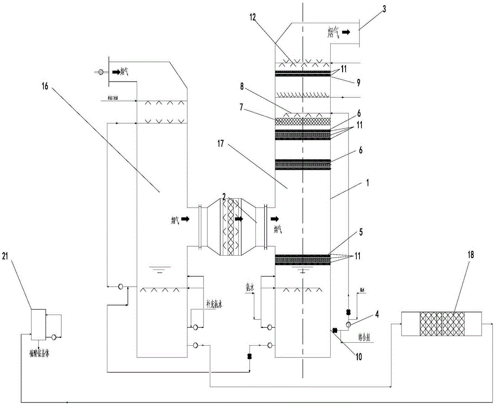
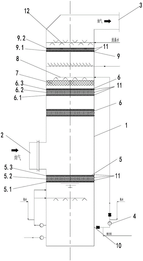
[0056] See figure 2 , The structure of the absorption tower is:

[0057] The synchronous desulfurization and denitrification reaction tower of the present invention includes a tower body 1, the top of the tower body is provided with a flue gas outlet 3, the middle of the tower body is provided with a flue gas inlet 2, and the bottom of the tower body 1 is provided with a circulating absorption liquid outlet 10, the circulating absorption liquid outlet 10 The circulating pump 4 is connected to the spray layer 8 on the upper part of the tower body, above the spray layer 8 an electrostatic defogging and reaction layer 9 is arranged in the tower body, and a washing layer is arranged above the electrostatic defogging and reaction layer 9; Below the spray layer 8 there is a packing layer 7 in the tower body, and at least one layer of absorption and electrochemical reaction layer 6 is arranged below the packing layer 7 (in this embodiment, there are two layers, two adjacent layers of ab...


PUM


Abstract

The invention discloses a process for synergic removal of flue gas pollutants through complexing absorption synchronous electrolytic reduction. The technical scheme is that the process comprises the steps that flue gas is pressurized and then fed into a concentrating tower to react; the flue gas coming out of the concentrating tower is fed into an absorption tower to be in reverse contact reaction with circulating absorption liquid sprayed out of a spraying layer on the upper portion of the tower and then is discharged out of the top of the absorption tower; part of concentrated solution at the bottom of the concentrating tower undergoes iron removal and then is fed into an ammonium sulfate crystallization system; the circulating absorption liquid sprayed out of the spraying layer is in reverse contact reaction with the flue gas downwards and then enters the bottom of the absorption tower through an electrolytic regeneration layer below a flue gas inlet, and a cathode layer, an anode layer and a cathode layer are sequentially arranged on the electrolytic regeneration layer from top to bottom. Each electrode layer is of a net structure made of a conductive material, every two adjacent electrode layers are insulated from each other, and the electrolytic regeneration layer is connected with a power supply through a binding post installed on the tower wall. The process is simple, high in reaction efficiency, low in running and investment cost, small in occupied space and particularly suitable for coordinating management of multiple flue gas pollutants.

Description

Technical field [0001] The invention relates to a flue gas treatment process, in particular to a flue gas pollutant synergistic removal process of complex absorption and simultaneous electrolytic reduction, and is particularly suitable for flue gas sulfur dioxide, nitrogen oxides, fine particulate matter, dioxins, etc. Coordinated treatment of multiple pollutants. Background technique [0002] There are many types of flue gas desulfurization and denitration technologies, and the engineering application of individual desulfurization or denitration technologies is becoming more and more perfect. However, the application of multi-pollutant cooperative control technology for flue gas is less. At present, in addition to the more mature adsorption method, other collaborative control technologies for engineering applications, especially the multi-pollutant collaborative control technology of flue gas wet method have not been reported. Wet flue gas synchronous desulfurization and denit...

Claims


Application Information

Patent Timeline
Patent Type & Authority Applications(China)
IPC IPC(8): B01D53/78B01D53/60B01D53/70B01D53/96B03C3/09B01D53/32
Inventor 向晓东吴高明幸福堂陈旺生卫书杰
Owner WUHAN UNIV OF SCI & TECH
Why Eureka
Try Eureka