

Ceramic grinding segment for cement grinder and preparation method of ceramic grinding segment
A grinding machine and grinding segment technology, applied in the field of cement processing, can solve the problems of poor high temperature resistance, insufficient strength, low grinding body hardness, etc., and achieve the effects of long replacement period, good bonding force and high melting point
- Summary
- Abstract
- Description
- Claims
- Application Information
AI Technical Summary
Problems solved by technology
Method used
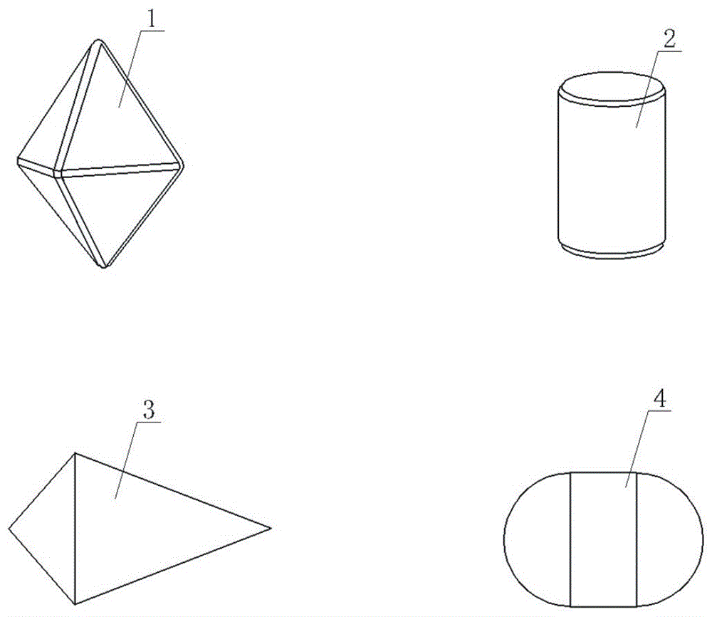
Image

Examples
Embodiment 1
[0034]The ceramic grinding section of the cement grinder contains 92% of alumina, 0.5% of tungsten carbide, 0.8% of calcium carbonate, 1.2% of magnesium carbonate, 2% of titanium nitride, 2.5% of silicon dioxide and 1% of zirconia by weight percentage. Prepared as follows:
[0035] (a) Batching: get all ingredients by weight percentage; configure PVA solution simultaneously, proportioning is PVA:water=8:100;
[0036] (b) Ball milling:
[0037] (b1) Primary grinding: Add the ingredients calculated in step (a) to the primary grinding equipment, and add ball stones and water (the primary grinding balls can be Φ30-Φ50mm 92-high alumina isostatic balls, the same below) , the ratio is material: ball: water=1:2.5:0.7, stop grinding to slurry fineness D90≤8 micron, cross 40 mesh sieves and go out grinding;
[0038] (b2) Fine grinding: Add the slurry obtained in step (b1) into the fine grinding equipment, and add ball stones and water (fine grinding ball stones can be 92-high alumina...
Embodiment 2
[0047] The ceramic grinding section of the cement grinder contains 95% of alumina, 0.5% of tungsten carbide, 0.8% of calcium carbonate, 1.2% of magnesium carbonate, 0.5% of titanium nitride, 1% of silicon dioxide and 1% of zirconia by weight percentage. Prepared as follows:
[0048] (a) Batching: get all ingredients by weight percentage; configure PVA solution simultaneously, proportioning is PVA:water=7:100;
[0049] (b) Ball milling:
[0050] (b1) Primary grinding: Add the ingredients calculated in step (a) to the primary grinding equipment, and add ball stones and water in a ratio of material: ball: water = 1:2.5:0.75, until the slurry fineness D90≤8 Micron stop grinding, pass through a 40-mesh sieve for grinding;
[0051] (b2) Fine grinding: Add the slurry obtained in step (b1) to the fine grinding equipment, and add ball stones and water in a ratio of material: ball: water = 1:3:0.75, until the fineness of the slurry is D50≤1.5 microns 、Stop grinding after D90≤3.2 micr...
Embodiment 3
[0060] The ceramic grinding section of the cement grinder contains 92% of alumina, 2% of tungsten carbide, 1.7% of calcium carbonate, 1% of magnesium carbonate, 0.5% of titanium nitride, 2% of silicon dioxide, and 0.8% of zirconia by weight percentage. Prepared as follows:
[0061] (a) Batching: get all ingredients by weight percentage; configure PVA solution simultaneously, proportioning is PVA:water=10:100;
[0062] (b) Ball milling:
[0063] (b1) Primary grinding: Add the ingredients calculated in step (a) to the primary grinding equipment, and add ball stones and water in a ratio of material: ball: water = 1:2.5:0.72, until the slurry fineness D90≤8 Micron stop grinding, pass through a 40-mesh sieve for grinding;
[0064] (b2) fine grinding: add the slurry obtained in step (b1) to the fine grinding equipment, and add ball stones and water in a ratio of material: ball: water = 1:2.5:0.75, until the fineness of the slurry is D50≤1.5 microns 、Stop grinding after D90≤3.2 mi...
PUM
 Abstract
Description
Claims
Application Information