
Ndfeb permanent magnet material with high magnetic energy product and high coercivity and manufacturing method thereof

A high coercive force and permanent magnet material technology, which is applied in the field of NdFeB permanent magnet materials with high magnetic energy product and high coercive force and its manufacturing field, can solve the problem of affecting the magnetic coupling effect of the liquid phase, high re-investment costs, and reduced Coercive force improvement effect and other issues, to achieve the effect of improving uniform deposition and transportation, reducing auxiliary supporting costs, and reducing local loss of magnetism

Active Publication Date: 2016-09-21
ORIENT MAGNET TECH OMT
View PDF3 Cites 24 Cited by
  • Summary
  • Abstract
  • Description
  • Claims
  • Application Information

AI Technical Summary

Problems solved by technology

There are three main types of existing grain boundaries: one is to use powder and slurry containing heavy rare earths to coat the surface of the substrate, and through physical contact diffusion to realize the diffusion of heavy rare earth elements along the grain boundaries and increase the coercive force, thereby improving Temperature resistance; but its disadvantage: the coating will stick to the substrate, resulting in the need for increased grinding
Due to the need to reprocess the surface layer, it is inevitable to reduce the effect of improving the coercive force. At the same time, the existing tests show that the diffusion depth of the grain boundary is generally within 500μm when the remanence is not greatly reduced. Grinding and fine grinding will result in a loss of at least 100 μm on both sides
Since the heavy rare earth diffuses at the boundary according to the concentration gradient, the effect is the best near the concentration of the diffusion source, and the processing will lead to a significant decrease in the temperature resistance; and due to the uneven surface, it will cause the problem of processing inclination, resulting in the expansion of the magnetic declination. That is to say, the consistency of the magnetic field in the orientation direction of the magnetic steel will deteriorate, which will affect the maximum torque and residual torque of the motor; because the surface is coated with a layer, only a small part of the actual diffusion will result in waste of diffusion materials and high production costs; When the liquid phase temperature is above 650°C, the liquid phase of the permanent magnet material will be volatilized, and eventually the material will inevitably lose the liquid phase locally, resulting in the direct integration of the pores and the main phase grains, and the loss of the demagnetic coupling effect of the material. Affect the improvement of coercive force, more missing will easily lead to partial loss of magnetism of the material, especially for high magnetic energy product grades, the liquid phase itself is less than that of low magnetic energy product grades, because the liquid phase is a non-magnetic phase, high magnetic energy The product is actually obtained by increasing the volume fraction of the magnetic phase, which is less than the conventional brand rare earth phase
The second category is to use methods such as evaporation or magnetron sputtering to form a thin layer of heavy rare earth metal layer (generally about 30 μm) on the surface of the substrate by physical or chemical methods. The method needs to increase the corresponding equipment, and the sputtering processing capacity is limited, so it is not easy to mass-produce; at the same time, the diffusion source has only a thin layer on the surface, which cannot continuously provide a high-concentration diffusion source, which affects the diffusion effect; and due to the long-term high-temperature diffusion, It leads to liquid phase volatilization, and it is easy to produce liquid phase loss locally for high magnetic energy product grades, which affects the improvement of local coercive force. In the case of loss, it is easy to lose magnetism locally
The third category is that the heavy rare earth metal is not in contact with the substrate, and the heavy rare earth is formed into a gaseous state at a certain temperature (generally 800 ° C ~ 1100 ° C) and a certain low vacuum, and diffuses continuously to the surface of the substrate, deposits and diffuses. , and the diffusion time is long, its disadvantages: this type of diffusion generally diffuses at a higher temperature for a long time, because above 650 ° C, the NdFeB permanent magnet substrate will have a liquid phase, and it will be higher than the liquid phase for a long time Under the condition of phase temperature, the liquid phase of the substrate will continue to volatilize, which will eventually lead to a decrease in the liquid phase, which will cause insufficient local existence of the substrate, which will affect the magnetic coupling effect of the liquid phase, and affect the improvement of the coercive force, and the longer the diffusion time, the local existence The greater the number of missing liquid phases, the final coercive force cannot be further improved; at the same time, due to the high temperature and low vacuum conditions, the heavy rare earths from the diffusion source are continuously volatilized in the form of vapor, and in the case of obtaining a higher coercive force , Long-term volatilization leads to serious loss of heavy rare earths in the diffusion source. Although a molybdenum box with tightness and small deformation is used as a container, the existing molybdenum box with better sealing size is 200mm*100mm*50mm, and its price exceeds 4000 For a conventional 300kg vacuum sintering furnace, the number of boxes exceeds 50 boxes, and the value of molybdenum boxes required for a sintering furnace exceeds 200,000 yuan. High, additional cost; even if a well-sealed molybdenum box is used, due to the low vacuum and high temperature, the volatilization and waste of heavy rare earths are inevitable; although heavy rare earth metals are deposited on the surface of the molybdenum box, it can be used after heating , but because rare earth metals are easy to react with water and oxygen, it is necessary to add additional protective devices, which will increase additional costs; There will be adhesion and grinding treatment is required; long-term high-temperature diffusion will cause the high concentration of heavy rare earth Dy or / and Tb at the grain boundary to exchange with Pr / Nd in the main phase crystal, and diffuse into the main phase. Dy2Fe14B and Tb2Fe14B with low remanence or low magnetic energy product are formed. The saturation magnetic polarization is lower than 1 / 2 of Nd2Fe14B. The longer the diffusion time, the more Dy2Fe14B and Tb2Fe14B will be produced. When it reaches a certain level, the final product Remanence and energy product will be significantly reduced

Method used


Image

  • Ndfeb permanent magnet material with high magnetic energy product and high coercivity and manufacturing method thereof
  • Ndfeb permanent magnet material with high magnetic energy product and high coercivity and manufacturing method thereof
  • Ndfeb permanent magnet material with high magnetic energy product and high coercivity and manufacturing method thereof

Examples


Embodiment 1

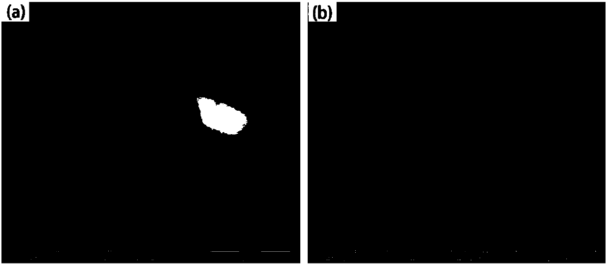
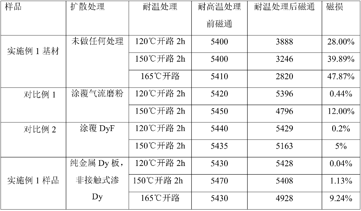
[0031] Matrix preparation: the rest of the composition is Nd28.3Tb2.5B0.96Cu0.05Co0.5Zr0.13Ga0.25Fe, using the flake technology, the average thickness of the flakes is 0.3mm at the pouring temperature of 1400 ℃, and the flakes are prepared by the hydrogen crushing process Hydrogen crushed powder with a hydrogen content of 1200ppm, added with 0.06wt% antioxidant and 0.1wt% lubricant and mixed for 60 minutes, prepared a fine powder with an average particle size of 3.1±0.15μm by jet mill, and then under the condition of 1.8T magnetic field Carry out orientation magnetization, and sinter at 1073°C for 5h, then keep at 900°C for 2h for the first step of aging, and then keep at 500°C for 5h for the second step of aging, prepare the blank, and then add the blank and process it into 20*18.8* The substrate sample is 1.8mm, and the surface roughness is Ra: 0.4μm, and the oxygen content in the center of the magnet is 1200ppm. Such as figure 1 As shown in Figure a: after sintering, there...

Embodiment 2

[0036] The blank prepared in Example 1 is processed into a sample of 20*18.8*16mm, and the surface roughness is Ra: 5 μm, and the vacuum degree is 3.5*10 -3 Pa, the temperature is 650°C for 5 hours of diffusion, after completion, the vacuum degree is 3.5*10 -3 Pa, the temperature is 100 ℃ diffusion 5h.

[0037] Then, the diffusion process was used for 5 cycles to prepare the required material of Example 2. Others are the same as embodiment 1.

Embodiment 3

[0039] The blank prepared in Example 1 was processed into a sample of 20*18.8*1mm, and the surface roughness was Ra: 0.2μm, and the vacuum degree was 0.5Pa, and the temperature was 950°C for 2 hours. After completion, carry out The vacuum degree is 0.5Pa, and the temperature is 500℃ for 5h.

[0040] Then, the diffusion process was used and circulated 3 times to prepare the required material of Example 3, and the others were the same as Example 1.


PUM

PropertyMeasurementUnit
Rough surfaceaaaaaaaaaa
Thicknessaaaaaaaaaa
Surface roughnessaaaaaaaaaa

Abstract

The invention belongs to the technical field of permanent magnet materials, and claims a Ndfeb permanent magnet material with high magnetic energy product and high coercivity. Component of the Ndfeb permanent magnet material is RE1xRE2yFzBwMmHn, wherein RE1 is selected from one or more than two of Pr, Nd, Ho, Gd, La and Ce, RE2 is selected from one or two of Dy and Tb, B is selected from one or two of boron and carbon, M is selected from one or more than two of Al, Cu, Zr, Nb, Ga, Si, Mo and Ti, H is an oxygen element, the rest is F, and F is selected from one or more than two of transition elements Fe, Co and Ni; and a manufacturing method of the Ndfeb permanent magnet material is (1) sintering for preparing a blank, covering two sides of a base material with heavy rare earth plates, isolating the heavy rare earth plates from the base material with a molybdenum net, and placing the blank in a graphite material box after isolation; (2) performing deposition and diffusion under vacuum condition at high temperature; further performing solid-state atomic diffusion under vacuum condition at low temperature; (3) repeating the step (2) more than once.

Description

technical field [0001] The invention belongs to the technical field of permanent magnet materials, in particular to an NdFeB permanent magnet material with high magnetic energy product and high coercive force and a manufacturing method thereof. Background technique [0002] With the wide application of NdFeB permanent magnet materials in air-conditioning compressors and new energy vehicle motors, the requirements for high torque, high temperature resistance, and low cost of motors are becoming more and more obvious. [0003] In the case of low cost, it is difficult to achieve mass production of high energy product and high coercive force in the existing single alloy technology, especially when the energy product is greater than 45MGOe and Hcj is greater than 23kOe. For example, in the existing single alloy technology, for the magnetic energy product greater than 42MGOe and Hcj greater than 20KOe, under normal circumstances, it is necessary to add heavy rare earth Dy or / and T...

Claims


Application Information

Patent Timeline
IPC IPC(8): H01F1/057H01F1/08C23C10/28
CPCC23C10/28H01F1/0571H01F1/0577
Inventor 廖超王军文卢国安章文周学虎
Owner ORIENT MAGNET TECH OMT
Learn More