Method and device for simultaneously desulfurizing and denitrifying flue gas by photo-catalysis and oxidation
A photocatalytic oxidation, desulfurization and denitrification technology, applied in the field of simultaneous desulfurization and denitrification, can solve problems such as treatment capacity limitation
- Summary
- Abstract
- Description
- Claims
- Application Information
AI Technical Summary
Problems solved by technology
Method used
Image
Examples
Embodiment 1
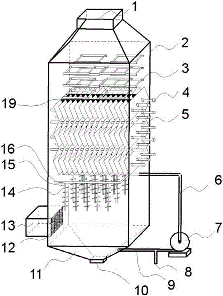
[0075] The structure of the flue gas catalytic oxidation simultaneous desulfurization and denitrification device of the present invention is as follows: figure 1 As shown, the device includes a housing 2, the housing 2 is designed as a rectangular parallelepiped in a shape suitable for an ultraviolet lamp, there is a smoke inlet 1 on the top of the housing 2, and a smoke outlet 13 on the side near the bottom . The housing 2 is provided with a vacuum ultraviolet lamp group, a photocatalytic bed and a sprayer along the gas flow direction. The gas flow direction is from top to bottom in the axial direction of the cylinder body 2. The vacuum ultraviolet lamp group has three layers, and each layer consists of 4 microwave electrodeless ultraviolet lamps 3 are arranged in a 2×2 rectangular array, and a photocatalytic bed is arranged close to the directly below the vacuum ultraviolet lamp group. The photocatalytic bed is composed of a sheet-shaped supported catalyst 5 and a 365nm ultr...
Embodiment 2
[0088] In case 2 as figure 1 The ultraviolet lamp group and the sprayer are installed as shown, the ultraviolet lamp group is specifically a three-layer microwave electrodeless ultraviolet lamp group, each layer is composed of 4 microwave electrodeless ultraviolet lamps 3 arranged in a 2×2 rectangular array, and the sprayer is composed of atomizing nozzles 14 , absorption liquid delivery pipe 6,9, sprayer branch pipe 15 and pump 7 are formed. In Example 2, an appropriate amount of tap water is preloaded into the liquid collection tank 11, and the ultraviolet lamp group and the pump 7 are turned on. After the system is in a stable state, 500 m³ / h SO is introduced from the flue gas inlet 1. 2 , NO and NO 2 The concentration of flue gas is 2600mg / m³1500mg / m³ and 100mg / m³ respectively, the moisture content of the flue gas is 8%, and the temperature is about 60°C. The exhaust gas detection results show that SO 2 and NOx removal rates were 41% and 97%, respectively.
Embodiment 3
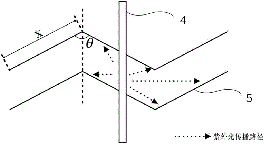
[0090] A photocatalyst bed and a sprayer are installed in the housing 2 as shown in the figure. The specific installation method of the photocatalyst bed is that the photocatalyst bed is composed of a sheet-shaped supported catalyst 5 and a 365nm ultraviolet lamp 4. Each sheet-shaped supported The catalyst has holes for rod-shaped 365nm ultraviolet lamps to penetrate, and multiple pieces of sheet-shaped supported catalysts are aligned and aligned in parallel to form a combination. Multi-layer combinations are stacked to form a photocatalyst bed, in which every two rectangular sheet-shaped supported catalysts are connected end to end. The angle θ between them is 110°. After the catalyst bed is installed, a 365nm ultraviolet lamp is inserted through the hole of the sheet-shaped supported catalyst 5. The atomizer consists of an atomizing nozzle 14, absorption liquid delivery pipes 6, 9, atomizer branch pipe 15 and a pump 7. Supported catalyst 5 was prepared by the impregnation me...
PUM
| Property | Measurement | Unit |
|---|---|---|
| Thickness | aaaaa | aaaaa |
Abstract
Description
Claims
Application Information
 - R&D
- Intellectual Property
- Life Sciences
- Materials
- Tech Scout
- Unparalleled Data Quality
- Higher Quality Content
- 60% Fewer Hallucinations
Browse by: Latest US Patents, China's latest patents, Technical Efficacy Thesaurus, Application Domain, Technology Topic, Popular Technical Reports.
© 2025 PatSnap. All rights reserved.Legal|Privacy policy|Modern Slavery Act Transparency Statement|Sitemap|About US| Contact US: help@patsnap.com


