
Method for synthesizing plasma composite photocatalyst

A plasma and composite light technology, applied in chemical instruments and methods, physical/chemical process catalysts, chemical/physical processes, etc., can solve the problem of low catalytic activity, and achieve the effect of good dispersion and stable properties

Inactive Publication Date: 2017-05-31
JIANGSU UNIV
View PDF2 Cites 6 Cited by
  • Summary
  • Abstract
  • Description
  • Claims
  • Application Information

AI Technical Summary

Problems solved by technology

Multi-metal oxide photocatalysts have been developed due to their unique electronic structures and diversification of energy band positions, and thus have become the focus of attention in the field of photocatalysis; however, the catalytic activity of existing multi-metal oxide photocatalysts is still very low, It cannot meet the needs of practical applications, so it is still a challenging subject to improve the separation efficiency of electrons and holes in such semiconductor materials through simple and efficient material preparation and modification methods to improve their photocatalytic activity.
[0003] Due to its special energy band structure and carrier transport characteristics, the heterojunction can effectively inhibit the recombination of photogenerated electrons and holes in the photocatalytic reaction, improve the quantum efficiency, and then greatly improve the catalytic activity of the photocatalyst. The exchange method and photoreduction method to prepare multi-metal oxides and Ag / AgCl to form heterostructures have not been reported. At present, there is no report on the construction of Ag / AgCl / AgBi(MoO 4 ) 2 Research on plasmonic photocatalyst and its plasmon resonance effect and its application in photocatalytic degradation of tetracycline

Method used


Image

  • Method for synthesizing plasma composite photocatalyst
  • Method for synthesizing plasma composite photocatalyst
  • Method for synthesizing plasma composite photocatalyst

Examples


Embodiment 1

[0018] Example 1 Ag / AgCl / AgBi(MoO 4 ) 2 Preparation of plasmonic photocatalyst

[0019] 1mmol of silver nitrate and 1mmol of bismuth nitrate were ultrasonically stirred and uniformly dispersed in 5mL of deionized water, and an aqueous solution containing 2mmol of sodium molybdate was added dropwise during the stirring process; microwave hydrothermal reaction was carried out at 160°C for 5 minutes in a microwave digestion apparatus with a power of 200W ; The product obtained is washed alternately three times with absolute ethanol and deionized water to obtain nanometer silver bismuth molybdate; the AgBi(MoO 4 ) 2 Ultrasonic dispersion in ethylene glycol, adding different amounts of potassium chloride, fully stirred for 4 hours, to obtain AgCl / AgBi (MoO 4 ) 2 The obtained sample is centrifuged and washed to remove residual ethylene glycol; the obtained sample is dispersed in deionized water and irradiated by a xenon lamp for 30 minutes. After the reaction is completed, the p...

Embodiment 2

[0020] The characterization analysis of the prepared plasma photocatalyst of embodiment 2

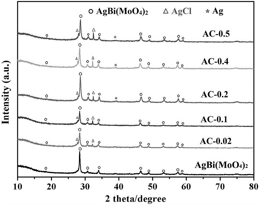
[0021] Such as figure 1 As shown, it can be seen from the figure that the compounded sample has Ag, AgCl, AgBi(MoO 4 ) 2 The characteristic peaks indicate that we have successfully prepared Ag / AgCl / AgBi(MoO 4 ) 2 plasmonic photocatalyst.

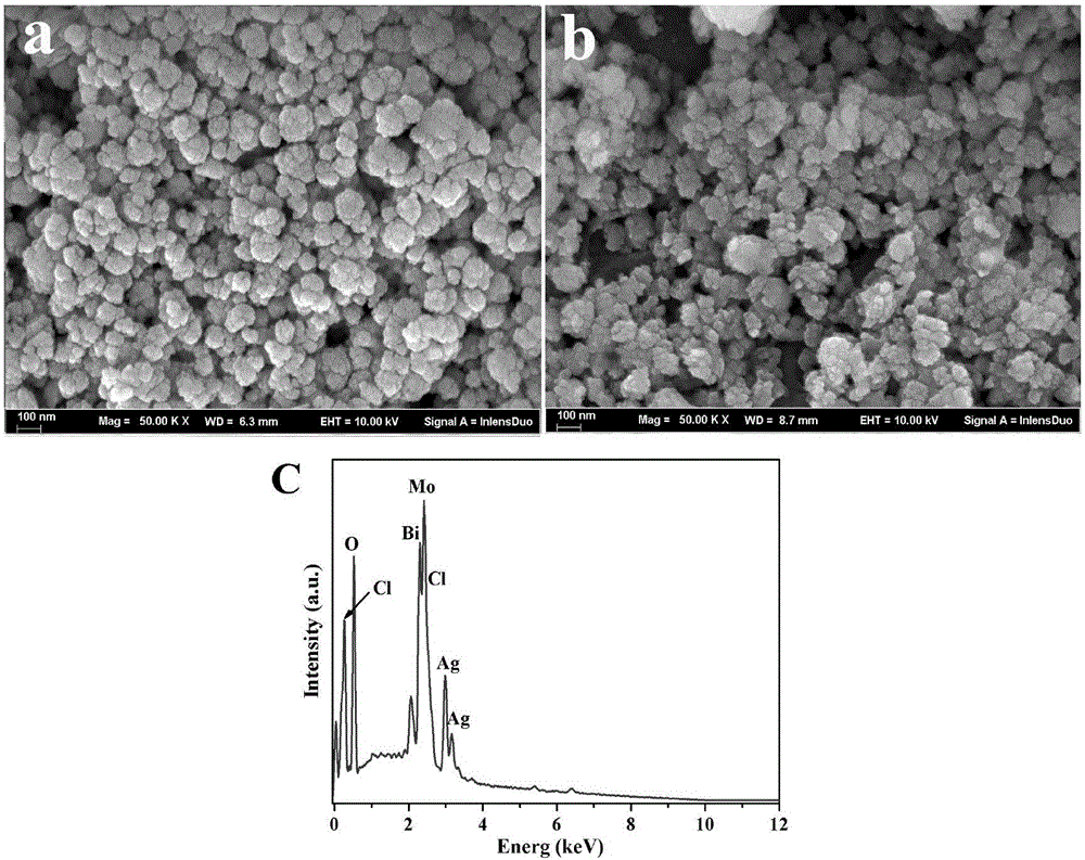
[0022] Such as figure 2 As shown in (A), pure AgBi(MoO 4 ) 2 It is a nanoparticle, assembled from nanoparticles with a size of 10-20nm, and the size is 100nm. In (B), it can be seen that AgBi(MoO 4 ) 2 The surface of the nanoparticles becomes rough due to the influence of Ag / AgCl, and the shape is irregular. The size of the nanoparticles is 120nm. The spectrum in (C) shows the presence of Ag, Mo, Bi, Cl, and oxygen elements.

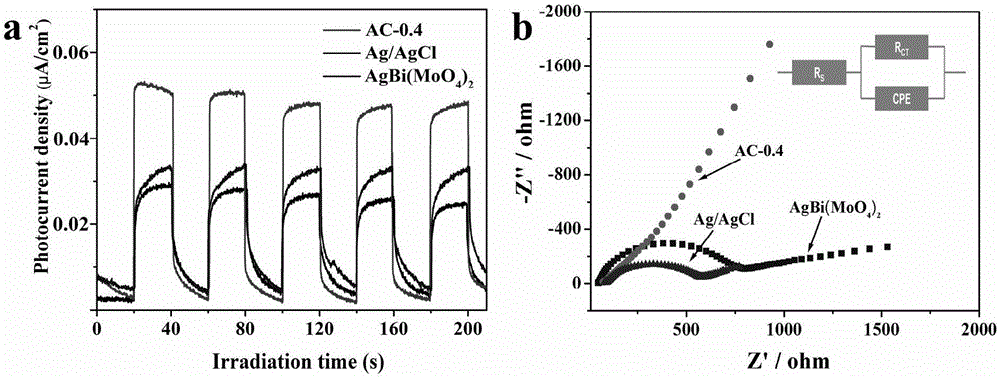
[0023] Such as image 3 As shown, (a) can clearly see that Ag / AgCl / AgBi(MoO 4 ) 2 The photocurrent intensity after illumination is significantly higher than that of Ag / AgCl and AgBi(MoO 4 ) 2 samples, showing the ...

Embodiment 3

[0024] Example 3 Ag / AgCl / AgBi(MoO 4 ) 2 Visible light catalytic activity experiments of plasmonic photocatalysts

[0025] (1) Prepare a tetracycline hydrochloride solution with a concentration of 10 mg / L, and place the prepared solution in a dark place.

[0026] (2) Weigh Ag / AgCl / AgBi(MoO 4 ) 2 Plasma photocatalyst 100mg (when AgBi(MoO 4 ) 2 The mass is 200mg, and the KCl moles are 0.02, 0.1, 0.2, 0.4 and 0.5mmol respectively. 1:15, 1:3, 2:3, 4:3 and 5:3), respectively placed in the photocatalytic reactor, add 100mL of the target degradation solution prepared in step (1), stir magnetically for 30min and wait for the photocatalytic reaction After the catalyst is evenly dispersed, turn on the water source and the light source to carry out the photocatalytic degradation experiment.

[0027] (3) Draw the photocatalytic degradation solution in the reactor every 10 minutes, centrifuge and use it for the measurement of ultraviolet-visible absorbance.

[0028] (4) by Figure 4 ...


PUM

PropertyMeasurementUnit
Sizeaaaaaaaaaa
Sizeaaaaaaaaaa
Sizeaaaaaaaaaa

Abstract

The invention relates to modification of multi-element metal oxide, in particular to a method for preparing an Ag / AgCl / AgBi(MoO4)2 plasma photocatalyst by taking sodium chloride, silver nitrate, bismuth nitrate and sodium molybdate as raw materials. The method comprises the following steps: taking the silver nitrate and the bismuth nitrate with equivalent substance amounts, and dispersing the silver nitrate and the bismuth nitrate into deionized water; then adding a sodium molybdate aqueous solution, stirring and mixing, then carrying out microwave hydrothermal reaction, and alternately cleaning obtained precipitation by using ethanol and the deionized water for three times; carrying out ultrasonic dispersion on obtained AgBi(MoO4)2 into ethylene glycol, adding sodium chloride of different substance amounts, and continuously stirring for 4 hours and carrying out photoreduction reduction; after the reaction is ended, filtering, washing and drying the precipitation to obtain the Ag / AgCl / AgBi(MoO4)2 plasma photocatalyst. An experiment of degrading tetracycline hydrochloride (TC) under visible light proves that the prepared composite photocatalyst has good photocatalytic activity.

Description

technical field [0001] The invention relates to multi-metal metal oxides, in particular to a kind of preparation of Ag / AgCl / AgBi(MoO 4 ) 2 A plasma photocatalyst method, especially a method for preparing a multi-metal oxide nanocomposite photocatalyst with simple preparation process, strong controllability and good visible light catalytic activity. Background technique [0002] Semiconductor photocatalysts can use solar energy to treat organic pollutants in water bodies or photolyze water, which has the characteristics of cleanliness, environmental protection and sustainability. Multi-metal oxide photocatalysts have been developed due to their unique electronic structures and diversification of energy band positions, and thus have become the focus of attention in the field of photocatalysis; however, the catalytic activity of existing multi-metal oxide photocatalysts is still very low, Therefore, it is still a challenging subject to improve the separation efficiency of ele...

Claims


Application Information

Patent Timeline
IPC IPC(8): B01J27/10C02F1/30C02F101/36
CPCC02F1/30B01J27/10C02F2101/36C02F2305/10B01J35/39
Inventor 延旭施伟东吕涛涛吴梓阳
Owner JIANGSU UNIV
Learn More