
Stack gate enhanced GaN high-electron-mobility transistor containing ferroelectric gate dielectric and preparation method
A high electron mobility, ferroelectric gate dielectric technology, applied in the field of microelectronics, can solve the problems of device characteristics and reliability impact, poor process repeatability, and can not be completely eliminated, so as to avoid secondary pollution and reduce process Effect of temperature, damage avoidance
- Summary
- Abstract
- Description
- Claims
- Application Information
AI Technical Summary
Problems solved by technology
Method used
Image

Examples
Embodiment 1
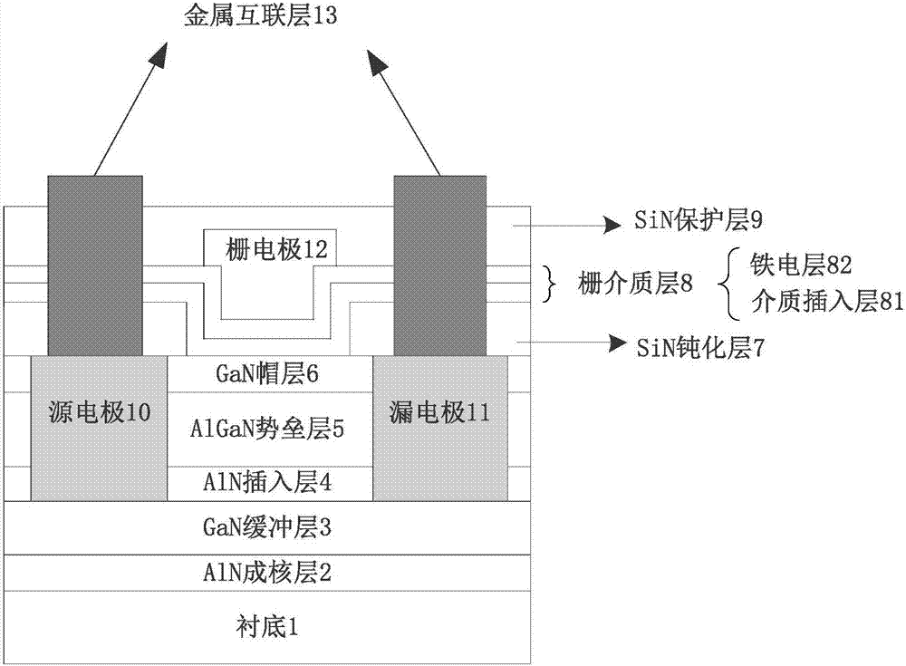
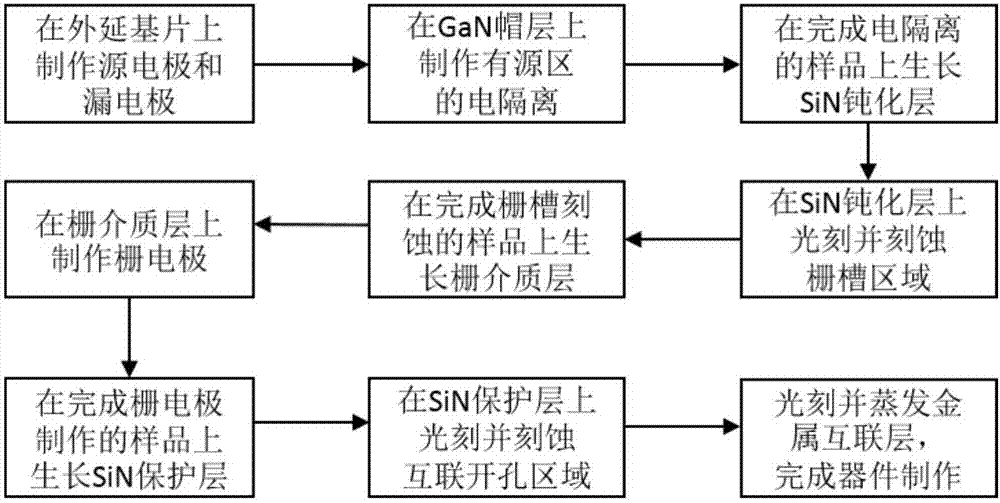
[0036] Embodiment 1, a stacked gate-enhanced GaN high electron mobility transistor with an AlN dielectric insertion layer 81 having a thickness of 2 nm and a HfZrO ferroelectric layer 82 having a thickness of 20 nm is fabricated on a sapphire substrate.
[0037]In the present invention, the initial material for fabricating high electron mobility transistors containing stacked gate enhanced GaN is a purchased epitaxial substrate, which sequentially includes a substrate 1, an AlN nucleation layer 2, a GaN buffer layer 3, AlN insertion layer 4 , AlGaN barrier layer 5 and GaN cap layer 6 .
[0038] In step 1, the source electrode 10 and the drain electrode 11 are fabricated on the GaN buffer layer 3 of the epitaxial substrate.
[0039] 1a) Photoetching the source electrode region and the drain electrode region on the GaN cap layer 6:
[0040] First, bake the epitaxial substrate on a hot plate at 200°C for 5 minutes;
[0041] Then, apply and spin the peeling glue on the GaN cap l...
Embodiment 2
[0116] Embodiment two, making Al on SiC substrate 2 o 3 The thickness of the dielectric insertion layer 81 is 1nm, and the thickness of the HfZrO ferroelectric layer 82 is 25nm. The stacked gate enhanced GaN high electron mobility transistor.
[0117] In step one, the source electrode 10 and the drain electrode 11 are fabricated on the GaN buffer layer 3 of the epitaxial substrate.
[0118] 1.1) Photoetching the region of the source electrode 10 and the region of the drain electrode 11 on the GaN cap layer 6:
[0119] The concrete realization of this step is identical with the step 1a) among the embodiment one;
[0120] 1.2) Evaporate the source electrode 10 and the drain electrode 11 on the GaN cap layer 6 in the region of the source electrode 10 and the region of the drain electrode 11 and on the photoresist outside the region of the source electrode 10 and the region of the drain electrode 11:
[0121] The concrete realization of this step is identical with the step 1b) ...
Embodiment 3
[0151] Embodiment 3, a laminated gate-enhanced GaN high electron mobility transistor with a thickness of 2.5 nm for the AlN dielectric insertion layer 81 and a thickness of 30 nm for the HfZrO gate dielectric 8 is fabricated on the Si substrate.
[0152] In step A, the source electrode 10 and the drain electrode 11 are fabricated on the GaN buffer layer 3 of the epitaxial substrate.
[0153] The specific implementation of this step is the same as step 1 in the first embodiment.
[0154] Step B, photoetching the electrical isolation region of the active region on the GaN cap layer 6 , and using an ion implantation process to fabricate the electrical isolation of the active region of the device.
[0155] The specific implementation of this step is the same as step 2 in the second embodiment.
[0156] In step C, a SiN passivation layer 7 is grown on the source electrode 10 , the drain electrode 11 and the GaN cap layer 6 in the active region by PECVD.
[0157] C1) Clean the sur...
PUM
 Abstract
Description
Claims
Application Information