
Double-electrode perovskite solar battery and preparation method thereof

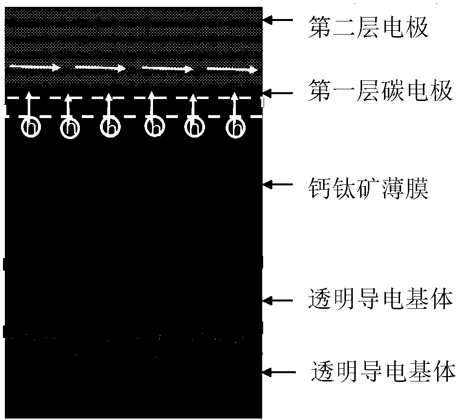
A technology for solar cells and double-layer electrodes, applied in circuits, photovoltaic power generation, electrical components, etc., can solve the problem of reduced contact area, increased probability of electron and hole recombination in perovskite thin films, and inability to take into account the contact of perovskite thin films and the Carbon electrode conductivity and other problems, to achieve the effect of improving performance and good lateral charge transfer function

Active Publication Date: 2018-04-13
咸阳瞪羚谷新材料科技有限公司
View PDF4 Cites 8 Cited by
  • Summary
  • Abstract
  • Description
  • Claims
  • Application Information

AI Technical Summary

Problems solved by technology

However, due to the large size of graphite, generally 5-20 μm, the contact area between the carbon electrode and the perovskite film is greatly reduced, and there are a large number of uncontacted areas between the perovskite film and the carbon electrode.
Because the transmission distance of charges in perovskite is generally less than 1 μm, the graphite sheets added in order to take into account the lateral conductivity, resulting in a large number of uncontacted areas of micron level, some even 10 μm, resulting in electrons and voids in the perovskite film. The probability of hole recombination is greatly increased, which is not conducive to the timely export of holes
Therefore, the current method cannot take into account the contact between the perovskite film and the carbon electrode and the conduction of the carbon electrode at the same time. Therefore, it is of far-reaching significance to find a suitable method to improve the current problem.

Method used


Image

  • Double-electrode perovskite solar battery and preparation method thereof
  • Double-electrode perovskite solar battery and preparation method thereof
  • Double-electrode perovskite solar battery and preparation method thereof

Examples


Embodiment 1

[0044] 1. On the ITO (tin-doped indium oxide) substrate, spin-coat TiO 2 Precursor, sintered at 450°C for half an hour to form TiO 2 (electron transport layer);

[0045] 2. In TiO 2 Spin-coat FAPbI on 3 Precursor. Dry to prepare a layer of film, that is, perovskite film;

[0046] 3. Prepare carbon paste A, wherein the conductive fine filler is 50nm carbon black particles, the binder is polyacrylate, and the solvent is chlorobenzene; the mass ratio of conductive fine filler to adhesive is 5:1; the mass of solid phase and solvent The ratio is 1:2.

[0047] 4. Scrape a layer of carbon paste A with a thickness of about 3 μm on the perovskite film with a doctor blade method, and then place it on a 100° C. electric heating plate to dry for 10 minutes to obtain the first layer of electrodes.

[0048] 5. On the first layer of electrodes, scrape a layer of directly purchased commercial carbon paste with a thickness of about 15 μm with a thickness of about 15 μm, and then place it...

Embodiment 2

[0051] 1. On the FTO (fluorine-doped tin oxide) substrate, spin-coat SnO 2 Precursor, sintered at 450°C for half an hour to form TiO 2 (electron transport layer);

[0052] 2. On SnO 2 Spin-coat MAPbI on 3 (methylammonium lead iodide) precursor. Dry to prepare a layer of film, that is, perovskite film;

[0053] 3. Prepare carbon paste A, wherein the conductive fine filler is 80nm carbon microspheres, the binder is polyacrylic resin, and the solvent is propylene glycol acetate; the mass ratio of conductive fine filler to binder is 4:1; solid phase and The mass ratio of solvents is 2:1.

[0054] 4. Scrape a layer of carbon paste A with a thickness of about 15 μm on the perovskite film with a scraper method, place it on the first layer of electrodes, and then place it at a temperature of 100 ° C for 15 minutes, and cover it with a layer of graphite paper as the second layer. Layer carbon electrodes, that is, perovskite solar cells made of double-layer electrodes.

[0055] T...

Embodiment 3

[0057] 1. On the FTO substrate, sputter 50nm ZnO film to form TiO 2 (electron transport layer);

[0058] 2. Spin-coating MAPbI on ZnO 3 Precursor. Dry to prepare a layer of film, that is, perovskite film;

[0059] 3. Prepare carbon paste A, wherein the conductive fine filler is carbon fiber with a diameter of 30nm, the binder is polyacrylic acid resin, and the solvent is propylene glycol acetate; the mass ratio of conductive fine filler to binder is 6:1; solid phase and solvent The mass ratio is 1:1.

[0060] 4. Scrape a layer of carbon paste A with a thickness of about 5 μm on the perovskite film with a doctor blade method, and then place it on a 100° C. electric heating plate to dry for 15 minutes to obtain the first layer of electrodes.

[0061] 5. On the first layer of electrodes, use a screen printing layer of commercial conductive silver paste (Saiya paste 01L-2200) with a thickness of about 10 μm, and dry at 80°C for 20 minutes to form a perovskite solar cell with d...


PUM

PropertyMeasurementUnit
Particle sizeaaaaaaaaaa
Thicknessaaaaaaaaaa
Diameteraaaaaaaaaa

Abstract

The invention discloses a double-electrode perovskite solar battery and a preparation method thereof. The battery includes a transparent conducting substrate, a semiconductor electron absorption layer, a perovskite thin film, (a hole transfer layer) and a double-layer carbon electrode superposed in sequence. As for the double-layer carbon electrode, the first layer electrode is a structural layerhaving charge selective absorption and longitudinal transmission functions and capable of increasing the contact area between perovskite or the hole transfer layer and the carbon electrode, so that alarge size of a micron order non-contact area is avoided and charge transmission distance is reduced, and holes can be extracted timely and recombination of electrons and the holes is reduced; the second layer electrode is a structural layer having a good transverse charge transmission function and facilitating timely converged exporting of holes in the electrode, so that the battery efficiency isimproved. According to the invention, good contact of the carbon electrode in the perovskite solar battery and perovskite and the electrical conductivity of the carbon electrode are both taken into account, so that advantages of simple preparation, good economical performance and practicability and batch production convenience are achieved.

Description

technical field [0001] The invention relates to the fields of material science technology, thin film preparation technology and solar cell preparation technology, in particular to a perovskite solar cell with double-layer electrodes and a preparation method thereof. Background technique [0002] As the problems of environmental pollution and energy depletion become more and more serious, the utilization of clean energy such as solar cells is a current research hotspot and an inevitable trend of future development. In recent years, organo-metal halides with a perovskite structure, as a light-absorbing material, have attracted great attention in the photovoltaic field due to their excellent properties, and have achieved rapid development. The traditional perovskite battery is composed of a transparent conductive substrate, an electron transport layer, a perovskite film, a hole transport layer (HTM), and a cathode conductive layer. Currently, the highest certified efficiency of...

Claims


Application Information

Patent Timeline
IPC IPC(8): H01L51/44H01L51/48
CPCH10K30/10H10K30/81Y02E10/549Y02P70/50
Inventor 杨冠军楚倩倩丁斌黄世玉李长久李成新
Owner 咸阳瞪羚谷新材料科技有限公司
Learn More