Catalyst system for preparing fuel oil from shale oil through catalytic hydrogenation and use method of catalyst system

A catalytic hydrogenation and catalyst technology, which is applied in the chemical industry, can solve the problems of easily destroying the acid center of the hydrogenation catalyst, high production costs, and decreased device stability, and achieves extended effective reaction time, low safety performance requirements, and production. The effect of cost reduction

Active Publication Date: 2018-05-04
FUSHUN XINRUI CATALYST
View PDF5 Cites 2 Cited by
  • Summary
  • Abstract
  • Description
  • Claims
  • Application Information

AI Technical Summary

Problems solved by technology

[0004] The unsaturated components in shale oil will react sharply to form colloid, and then high-temperature coking will block the catalyst pores or catalyst bed, resulting in an increase in system pressure difference, a decrease in device stability, and even forced shutdown
In addition, because shale oil itself is not as stable as crude oil, it is prone to produce metastable substances at high temperatures, and these metastable substances are prone to polymerization in the high-temperature, high-pressure hydrogen atmosphere in the reactor, further aggravating the coking phenomenon
Colloids and coking will cause catalyst activity to decrease, or even deactivate
In addition, due to the high nitrogen content in shale oil, which can reach 5000-18000 μg / g, in this case the NH in the reactor 3 The relative content of the hydrogenation catalyst will be quite high, which will easily destroy the acidic center of the hydrogenation catalyst, and cause the hydrogenation catalyst to deactivate rapidly and shorten the service life. It is necessary to continuously interrupt production to replace the catalyst, resulting in high production costs

Method used


Image

  • Catalyst system for preparing fuel oil from shale oil through catalytic hydrogenation and use method of catalyst system
  • Catalyst system for preparing fuel oil from shale oil through catalytic hydrogenation and use method of catalyst system
  • Catalyst system for preparing fuel oil from shale oil through catalytic hydrogenation and use method of catalyst system

Examples


Embodiment Construction

[0028] The present application will be further described in detail below in conjunction with the examples. It should be understood that the specific embodiments described here are only used to explain the present application, but not to limit the present application.

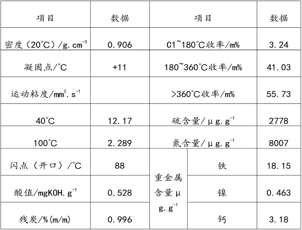
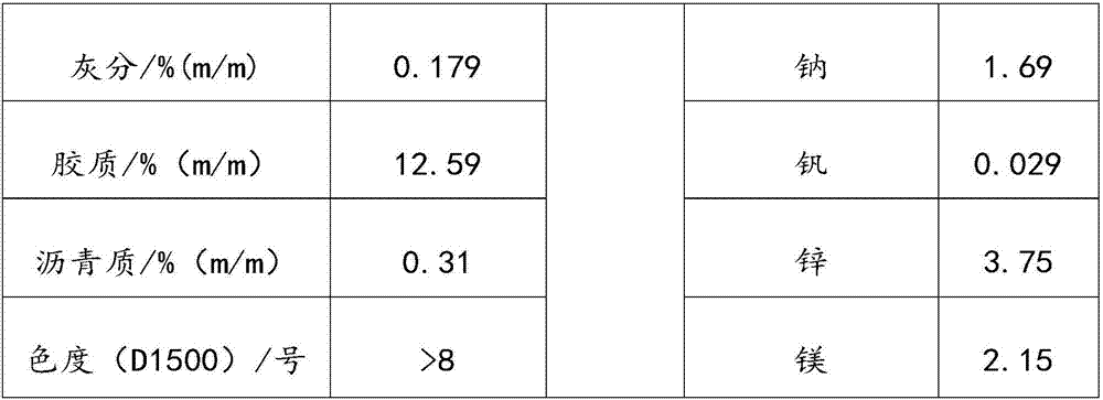
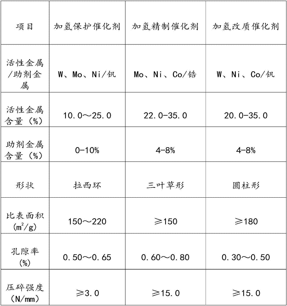
[0029] The invention provides a catalyst system for preparing fuel oil by catalytic hydrogenation of shale oil. Through the selection of carrier, active metal and additive metal, as well as the control of catalyst loading settings, porosity, bulk density, etc., the reaction system is easy to operate. The reacted metastable substances are reacted (these substances are coked at high temperature), reducing the intensity of the reaction and ensuring the smooth and orderly reaction; it solves the problem that the shale oil full fraction colloid and asphaltene high hydrogenation unit cannot operate for a long time At the same time, it also solves the problem of high nitrogen content and low sulfur content in the whole d...


PUM


Abstract

The invention relates to a catalyst system for preparing fuel oil from shale oil through catalytic hydrogenation and a use method of the catalyst system. The catalyst system comprises a hydrogenationprotection catalyst, a hydrogenation refining catalyst and a hydrogenation modification catalyst, wherein the hydrogenation protection catalyst comprises a first carrier, a first active metal and a first aid metal; the hydrogenation refining catalyst comprises a second carrier, a second active metal and a second aid metal; the hydrogenation modification catalyst comprises a third carrier, a thirdactive metal and a third aid metal; both the first carrier and the second carrier are macropore aluminum oxide; the third carrier is aluminum oxide with a modified molecular sieve; the first active metal, the second active metal and the third active metal are selected from one or more of W, Mo, Ni and Co in an oxidation state; and the first aid metal, the second aid metal and the third aid metal are selected from one or more of vanadium series meals, zirconium series metals or lanthanide series metals. By adopting the catalyst system and the method, the problems of coking and catalyst poisoning are effectively solved, and the catalyst system is low in cost and safe and stable.

Description

technical field [0001] The invention relates to the field of chemical industry, in particular to a catalyst system for preparing fuel oil by catalytic hydrogenation of shale oil and a use method thereof. Background technique [0002] Shale oil is a product produced by thermal decomposition of kerogen shale after thermal processing of its organic matter. It is similar to natural oil, but contains more unsaturated hydrocarbons than natural oil, and contains non-hydrocarbon organic compounds such as nitrogen, sulfur, and oxygen. These unsaturated hydrocarbons and non-hydrocarbon organic compounds are the main reasons for the increase of oil colloid and the formation of sediment, which lead to poor stability and black color. In addition, shale oil contains more inorganic impurities than petroleum. Shale oil is an important part of the energy industry and a supplementary energy source to natural petroleum. However, high heterocyclic aromatic hydrocarbons in shale oil hinder its...

Claims


Application Information

Patent Timeline
Patent Type & Authority Applications(China)
IPC IPC(8): B01J23/883B01J23/888B01J29/00B01J35/02B01J35/10C10G45/08C10G45/12
CPCB01J23/883B01J23/8885B01J29/00B01J35/0026B01J35/023B01J35/1019B01J2229/183C10G45/08C10G45/12C10G2300/70
Inventor 罗继刚陈小斌张笑剑柴平平罗继庆耿强梁博
Owner FUSHUN XINRUI CATALYST
Why Eureka
Try Eureka