Electropolishing device for inner wall of stainless steel pipe

A technology of electrolytic polishing and stainless steel tubes, which is applied in the direction of electrolytic process and electrolytic components, can solve the problems of deteriorating air bubble outflow effect, failure to reach current density, high leakage risk, etc., and achieve good process stability and consistency, economic benefits and Good safety and compact equipment structure

Active Publication Date: 2018-09-25
宣城品宙洁净科技有限公司
View PDF10 Cites 3 Cited by
  • Summary
  • Abstract
  • Description
  • Claims
  • Application Information

AI Technical Summary

Problems solved by technology

Such an electrolytic polishing process has several serious defects: First, since the inner surface of the entire steel pipe is electrolytically polished at the same time, the current that the slender cathode conductor structure can withstand is very limited, and the result is that it is impossible to achieve the desired level at all. The required current density, and the smaller the diameter of the steel pipe, the more serious the problem
[0006] 1. The polishing effect of this scheme is poor: when the movement direction of the cathode is opposite to the flow direction of the electropolishing solution, the outflow effect of the bubbles will be deteriorated, which will seriously affect the polishing quality
The horizontally arranged structure of steel pipes is also prone to the situation that the electrolytic polishing solution cannot fill the entire pipe, which in turn leads to partial failure of normal electrolysis.
In addition, the amount of electrolyte at the two ports of the steel pipe is difficult to control, and it is difficult to obtain the same current density and polishing time as the middle section of the steel pipe, and the polishing effect is difficult to meet the semiconductor industry standard
[0007] 2. The equipment occupies a large area: the standard length of the electropolishing tube required by the semiconductor industry is 6 meters. In the prior art, the steel tube is placed horizontally during electropolishing, and the cathode and the extension rod inserted into the steel tube are both rigid long conductors. This structural feature determines that the overall equipment length must exceed 12 meters
In the case of limited space, such a layout is difficult to produce a large number of steel pipes at the same time. In practical applications, only two steel pipes can be produced at the same time. The cost is high and the efficiency is very low, and the required length of the equipment is too long. Affect the efficiency of space utilization
[0008] 3. It is difficult to achieve the ideal flow rate of the electrolytic polishing solution in the tube: when using the existing technology for electrolytic polishing, each steel pipe is responsible for pumping the electrolytic polishing solution by a separate acid-resistant high-temperature centrifugal pump, but the electrolytic polishing solution is relatively viscous, and its specific gravity often reaches 1.7 above
However, the characteristics of the centrifugal pump determine that the flow rate is too small and it cannot work stably at all, and it is also easy to overheat and damage the pump head because th

Method used


Image

  • Electropolishing device for inner wall of stainless steel pipe
  • Electropolishing device for inner wall of stainless steel pipe
  • Electropolishing device for inner wall of stainless steel pipe

Examples


Example Embodiment

[0055] Example 1

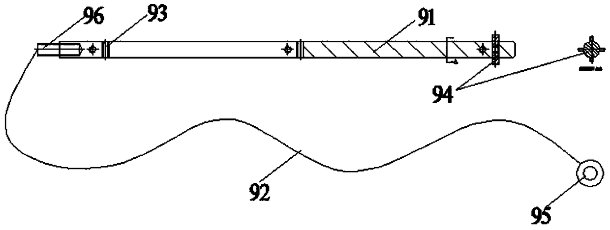
[0056] An electrolytic polishing equipment for the inner wall of stainless steel pipes. A copper anode assembly frame 1 is provided on the upper end of the equipment. The inclination angle of the copper anode assembly frame 1 is 5-15°, and 10 to 20 can be placed at one time Products, the bottom of the copper anode assembly frame 1 is equidistantly provided with several brackets for fixing the equipment, and the copper anode assembly frame 1 is equipped with several V-shaped grooves 2, which is suitable for steel pipe products with various outer diameters. , The upper part of the V-shaped groove 2 is provided with a pressing device 3, a steel pipe 4 is provided between the copper anode assembly frame 1 and the pressing device 3, and an extension is connected to both ends of the steel pipe 4 The steel pipe 5 has the same diameter as the steel pipe 4, the length of the steel pipe 5 is 50-100 cm, and the left end of the steel pipe 5 at the left end is provided with...

Example Embodiment

[0069] Example 2

[0070] 1. Production example of 316L stainless steel pipe with an outer diameter of 12.7 mm (1 / 2 inch):

[0071] 1.1. Place 10 316L raw material steel pipes with an outer diameter of 12.7 mm and a length of 6 meters on the copper anode assembly frame at one time (the raw material pipes are bright annealed);

[0072] 1.2. The upper and lower ports of all steel pipes use the quick-twist joint assembly to connect 304 extension steel pipes with a length of 800 mm and an outer diameter of 12.7 mm. There are 10 extension steel pipes at the upper and lower ends, and the 10 extension steel pipes at the lower end are connected with the electrolyte distributor through the quick-twist joint assembly. The upper extension steel pipe extends into the collector, and the upper port is open.

[0073] 1.3. The round copper rod with a diameter of 5 mm and a length of 800 mm is selected as the cathode body. A PTFE externally threaded rod with a diameter of 3 mm and a length of 9 mm i...

Example Embodiment

[0077] Example 3: Examples of effects of products or methods

[0078] In the above embodiment 2, 10 6-meter-long 316L stainless steel pipes were electrolyzed within 30 minutes, and a series of tests were performed after completing the conventional cleaning process.

[0079] 1. The inner surface roughness of each steel pipe is measured at 3 positions at both ends and the center. Each position is measured with a Japanese Mitutoyo SJ-210 roughness meter. The measured inner surface roughness data is as follows Figure 8 Shown.

[0080] 2. Cut all the steel pipes for visual inspection. The inner walls of the steel pipes are bright electrolytically polished surfaces without any visible defects.

[0081] 3. Based on the international standard test method SEMATECH Test Method 91060573B of the semiconductor industry, the AES oxide layer thickness analysis of the steel pipe samples is carried out, and the results are as follows Picture 9 Shown.

[0082] 4. Based on the international standard tes...


PUM

PropertyMeasurementUnit
Diameteraaaaaaaaaa
Lengthaaaaaaaaaa
Diameteraaaaaaaaaa

Abstract

The invention provides an electropolishing device for inner wall of stainless steel pipe, the upper end of the device is provided with a copper anode unit frame, the copper anode unit frame has an inclination angle of 5 to 15 degrees, and extension steel pipes are connected to both ends of a steel pipe, the left end of the extension steel pipe at the left end is provided with an electrolyte distributor, the electrolyte distributor is connected with a high-lift centrifugal pump through a pipeline, the right end opening of the extension steel pipe at the right end is connected with a collector,a flexible cathode is arranged in the steel pipe, a return pipe connected with an electrolyte tank is arranged at the bottom of the collector, a pressure relief pipeline is arranged between the upperend of the electrolyte tank and the outlet of the high-lift centrifugal pump, and a fully automatic control host and a high frequency pulse rectifier are arranged at the bottom of the right side of the copper anode unit frame. The device has compact structure, small floor space, high processing efficiency, good processing quality, convenient assembly and disassembly of components, long service life of the device and good economic benefits.

Description

technical field [0001] The invention relates to the technical field of integrated circuit chip manufacturing, in particular to an electrolytic polishing device for the inner wall of an ultra-high cleanliness stainless steel pipe used for transporting ultra-high-purity gas in the integrated circuit chip manufacturing industry. Background technique [0002] In the modern integrated circuit industry, the characteristic line width of the chip has reached the nanometer level. Therefore, ultra-high purity 316L stainless steel pipes must be used for the delivery of high-purity gases in the integrated circuit industry. The inner wall of this type of steel pipe must undergo high-quality electrolytic polishing, and the inner surface roughness must reach Ra 0.25 microns or even lower, otherwise, a very small amount of particles or impure substances will adhere to the rough inner wall, and the existence of such impurities It can cause the yield rate of the chip to drop significantly. ...

Claims


Application Information

Patent Timeline
IPC IPC(8): C25F7/00C25F3/24
CPCC25F3/24C25F7/00
Inventor 吴磊刚陶然
Owner 宣城品宙洁净科技有限公司
Why Eureka
Try Eureka