Mems sensor device for electric field measurement based on piezoelectric-magnetic anisotropic coupling structure

A technology of magnetic anisotropy and coupling structure, which can be used in measuring devices, electromagnetic field characteristics, measuring electrical variables, etc. It can solve the problems of poor temperature stability and serious temperature drift of photoelectric sensors, and achieve adjustable electric field sensing range, frequency response The effect of good characteristics and simple structure

Active Publication Date: 2020-12-18
TSINGHUA UNIV
View PDF7 Cites 0 Cited by
  • Summary
  • Abstract
  • Description
  • Claims
  • Application Information

AI Technical Summary

Problems solved by technology

However, due to the pyroelectric effect and thermal expansion of the material, the internal temperature stability of the photoelectric sensor is poor, the temperature drift is serious, and a complex temperature compensation circuit is required, which limits the application of the photoelectric sensor in complex and changeable environments.

Method used


Image

  • Mems sensor device for electric field measurement based on piezoelectric-magnetic anisotropic coupling structure
  • Mems sensor device for electric field measurement based on piezoelectric-magnetic anisotropic coupling structure
  • Mems sensor device for electric field measurement based on piezoelectric-magnetic anisotropic coupling structure

Examples


Embodiment 1

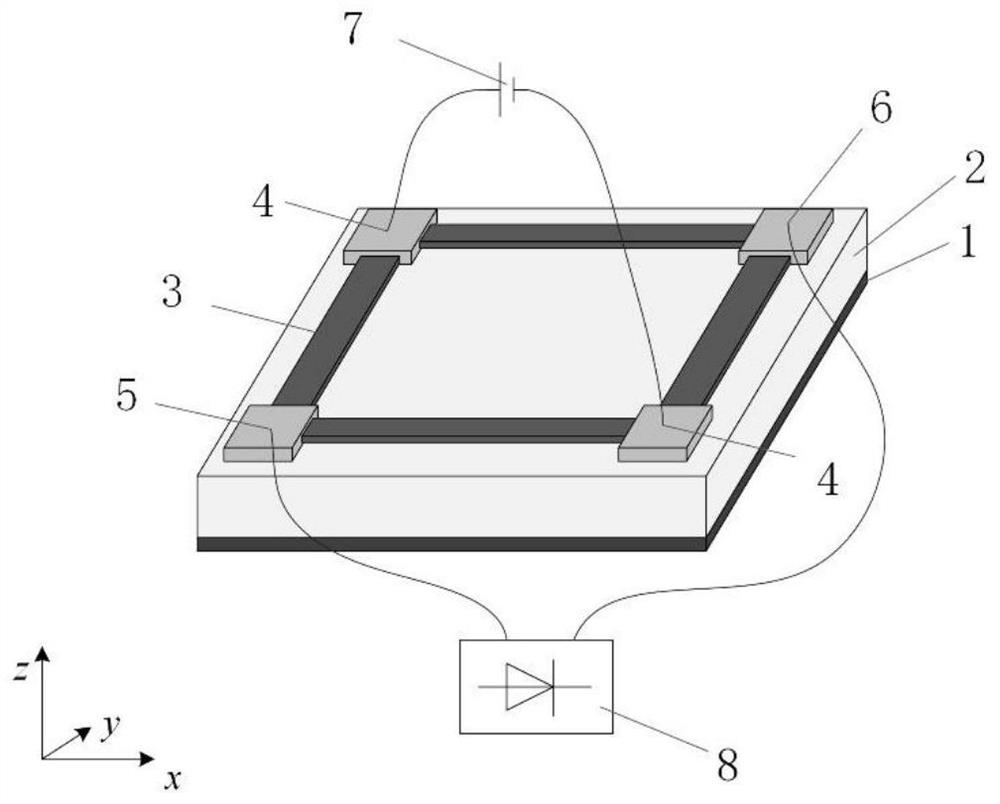
[0032]In the electric field measurement MEMS sensor device based on the piezoelectric-magnetic anisotropic coupling structure proposed by the present invention, the material selection basis of the bottom metal and the four metal electrodes is good conductivity, such as commonly used aluminum, copper, platinum, gold And other metals, the thickness of the material can range from tens of nanometers to several microns, and the processing method of the material can be a metal thin film micromachining process such as magnetron sputtering coating and chemical vapor deposition. Among them, the piezoelectric material can be a cylinder or a block piezoelectric material with a positive side prism, such as a relaxor ferroelectric crystal lead magnesium niobate titanate (PMN-PT) with a perovskite structure, lead titanium niobate zincate, etc. Lead zirconate titanate (PZN-PT), lead zirconate titanate (PZT) crystals, etc.; piezoelectric materials can also choose piezoelectric films, such as P...

Embodiment 2

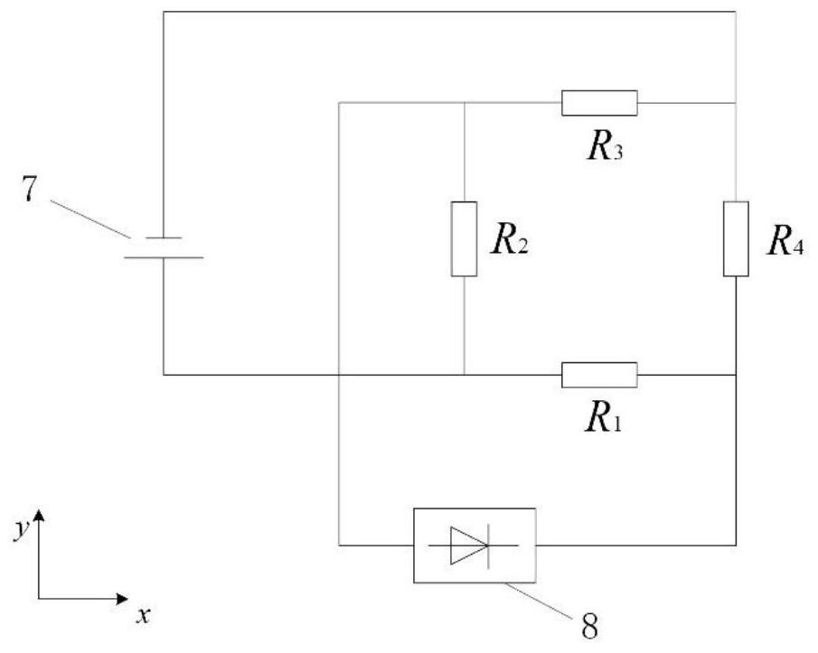
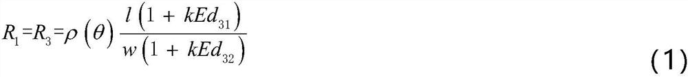
[0034] Such as figure 1 As shown, the length of the four ferromagnetic thin films is I, and the width is W. Assume that the electric field to be measured is along the thickness direction, which is consistent with the prepolarization direction of the piezoelectric material. Assuming that the piezoelectric effect is linear, it can be characterized by a piezoelectric constant coefficient, and the shear strain is neglected, then under the action of an external electric field E, the resistance value of the ferromagnetic film and the output voltage U o can be expressed as

[0035]

[0036]

[0037]

[0038] Among them, d 31 and d 32 are the piezoelectric constant coefficients of the piezoelectric material in the 1 direction (x direction in the coordinate system) and the 2 direction (y direction in the coordinate system), which can be found in the material parameter manual; the amplitude of the Wheatstone bridge DC power supply voltage source The value is U s ; ρ(θ) is ...


PUM


Abstract

The invention discloses a MEMS sensing device for electric field measurement based on a piezoelectric-magnetic anisotropy coupling structure. The device comprises piezoelectric materials. The bottom surface of the piezoelectric materials adheres to a bottom metal, and the top surface of the piezoelectric materials adheres to a ferromagnetic membrane and a metal electrode. The beneficial effect isthat: the device has a large measuring range, a high sensitivity, a fast transient response speed, an electric field measurement range with a wide band and a high field strength, a good temperature stability, a high integration degree and a small size; the device provides a high-performance, low-cost, safe and reliable electric field sensor for the fields of electric power systems, aerospace, meteorological monitoring and the like.

Description

technical field [0001] The invention relates to the field of high-performance intelligent instruments and meters in advanced manufacturing and automation-new sensors, in particular to an electric field measurement MEMS sensor device based on a piezoelectric-magnetic anisotropic coupling structure. Background technique [0002] In modern society, people's demand for electric energy is increasing day by day. In order to improve the quality of electric energy and increase the utilization rate of electric energy, it is very important to develop smart grid. The core technology of establishing a smart grid is to realize real-time feedback and dynamic adjustment of data information at the energy supply end, transmission end, and demand end. The construction of a smart grid sensor network can realize real-time monitoring of each node in the power grid generation, transmission, transformation, power supply and distribution system, which can not only optimize the allocation of power r...

Claims


Application Information

Patent Timeline
Patent Type & Authority Patents(China)
IPC IPC(8): G01R29/08
CPCG01R29/0878
Inventor 何金良薛芬胡军杨钧清王善祥韩志飞余占清曾嵘
Owner TSINGHUA UNIV
Why Eureka
Try Eureka