Process and device for separating acid gas by using hydration method

A sour gas and hydration technology, applied in separation methods, dispersed particle separation, sulfur compounds, etc., can solve the problems of increased energy consumption, complex production equipment, poor fluidity of hydrates, etc., to ensure that the equipment and treatment process are environmentally friendly and reduce The effect of energy consumption

Active Publication Date: 2019-03-05
CHINA PETROLEUM & CHEM CORP +1
View PDF14 Cites 4 Cited by
  • Summary
  • Abstract
  • Description
  • Claims
  • Application Information

AI Technical Summary

Problems solved by technology

The two-stage Claus + tail gas hydrogenation reduction + solvent absorption technology is mature, and the quality of the product sulfur is stable. However, due to the long process, large investment, high energy consumption, and high requirements for device safety control, and the Claus process can only handle high-concentration acid gases, it is difficult for There is no advantage in acid gas treatment in small refineries
Refinery acid gas contains H 2 In addition to S gas, it also contains a certain amount of CO 2 gas, during the production of soda sulfide, CO 2 The gas will produce Na with raw lye 2 CO 3 / NaHCO 3 Impurities cause blockage of process pipelines in the production process, resulting in the failure of long-term continuous operation of production equipment, and there are problems such as high alkali consumption and poor product purity.
CN103551018A discloses a method for purifying and recycling sulfur-containing tail gas, using barium sulfide to treat CO in the gas 2 Removed to obtain H 2 S gas can produce high-quality NaHS products, but it produces barium sulfite and barium carbonate precipitates, which are difficult to handle
Patent CN103754833A discloses a device and method for producing NaHS using refinery dry gas, using supergravity technology to perform selective desulfurization on dry gas to obtain 99% H 2 The purity of NaHS produced by S gas can reach more than 42%, but the raw material gas pretreatment process of this technology is long, the production equipment is complex, and the energy consumption of regeneration of rich absorption liquid is high
The NaHS production technology described in CN103446849A, CN103466559A and CN103638802A also faces the problems of complicated process, high energy consumption of amine liquid regeneration in acid gas pretreatment, etc.
However, the energy consumption of exothermic and endothermic energy during the formation and decomposition of hydrates is the main factor restricting the application of this technology.
In addition, the traditional hydrate method uses an aqueous solution for the liquid phase of gas separation, and the hydrates formed are generally in the form of crystals. The formed hydrates have poor fluidity and are easy to accumulate and block, which directly restricts the continuity and scale of hydrate-related technologies. application
Although there are related technologies that use granulation and hydrate slurry for transportation in order to solve the problem of hydrate fluidity, the granulation technology requires a dehydration process, and then uses a granulator to process the dehydrated hydrate, and the process is complicated. In the form of hydrate slurry, the hydrate and the unreacted hydrate solution are circulated and transported together to solve the fluidity problem, but when the hydrate is decomposed, the overall temperature of the mixed slurry needs to be raised, and then the overall temperature is lowered after decomposing and releasing gas. Greatly increased energy consumption and increased operating costs

Method used


Image

  • Process and device for separating acid gas by using hydration method
  • Process and device for separating acid gas by using hydration method

Examples


Embodiment 1

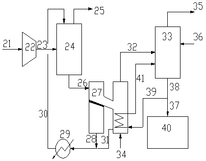
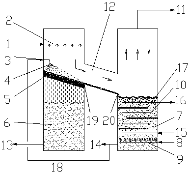
[0074] Acid gas volume Q=400Nm in a refinery 3 / h, pressure 0.7Mpa, where H 2 S volume fraction is 84%, CO 2 The volume fraction is 16%, and the remainder is hydrocarbons and other substances. use figure 1 The shown processing method and device process acid gas. Among them, the hydrate decomposer adopts figure 2 The structure of the resolver.

[0075] The operating conditions and treatment effects during the treatment process are as follows: the acid gas 21 is pressurized by the compressor 22 to 1.2Mpa and then introduced into the hydration reactor 24, where it reacts with the hydrate working fluid in the hydration reactor 24. The reaction conditions are: pressure 1.2 Mpa, temperature 5°C, hydrate working fluid consists of water, SDS accounting for 0.03% of the mass fraction of the aqueous solution, polyethylene glycol accounting for 10% of the aqueous solution, diesel oil with a volume ratio of 1 / 4 to water, and a molar ratio of water to water of 0.8% Span (sorbitan f...


PUM


Abstract

The invention discloses a process and a device for separating acid gases by using a hydration method. The device comprises a hydration reactor, a hydrate decomposer, an absorption reactor and a product tank; an acid gas feeding pipeline is connected with the gas-phase inlet of the hydration reactor, the liquid phase outlet of the hydration reactor is connected with the hydrate slurry inlet of thehydrate decomposer, and the cold-clear liquid outlet and the regenerated hydrate working fluid outlet of the hydrate decomposer are connected with the liquid-phase inlet of the hydrate reactor after passing through a cooler; the gas-phase outlet of the hydrate decomposer is connected with the gas-phase inlet of the absorption reactor, the gas phase outlet of the absorption reactor is connected with a purification gas outlet pipeline, and the liquid phase inlet of the absorption reactor is connected with an alkali liquor inlet pipeline. According to the invention, the energy in the whole process is fully utilized, heat absorption of hydrate decomposition and heat release of alkali method absorption are reasonably matched, and the energy consumption is greatly reduced.

Description

technical field [0001] The invention relates to a treatment method and device for acid gas, in particular to a technology for purification of acid gas containing carbon dioxide and hydrogen sulfide and recovery and utilization of pollutant resources. Background technique [0002] Refinery acid gas is a kind of processing tail gas produced in the process of petroleum processing, and its main component is H 2 S and CO 2 . Refinery acid gas mainly comes from sour water stripping, circulating hydrogen desulfurization, dry gas and liquefied gas desulfurization and other devices. Large-scale refineries have a large amount of acid gas (annual sulfur output > 5000t / a), and generally build acid gas treatment devices for sulfur production. 2 S for recycling. For small and medium-sized refineries (annual sulfur output <5000t / a), due to the small amount of acid gas, the cost of setting up sulfur facilities is relatively high. waste, and the combustion of SO 2 Environmental p...

Claims


Application Information

Patent Timeline
Patent Type & Authority Applications(China)
IPC IPC(8): B01D53/75B01D53/78B01D53/52B01D53/96C01B17/32C01B17/22
CPCB01D53/526B01D53/75B01D53/78B01D53/96B01D2251/00B01D2251/304B01D2251/604C01B17/22C01B17/32
Inventor 孟凡飞王海波彭德强陈新王璐瑶廖昌建
Owner CHINA PETROLEUM & CHEM CORP
Why Eureka
Try Eureka