
A compound eye microlens array and its preparation method

A micro-lens array and compound eye technology, which is applied to lenses, instruments, optics, etc., can solve the problems of poor flexibility, loss of field of view, and high cost of template manufacturing, and achieve the goal of improving receiving efficiency, reducing spherical aberration, and reducing field of view loss. Effect

Active Publication Date: 2020-08-18
HUAZHONG UNIV OF SCI & TECH
View PDF6 Cites 0 Cited by
  • Summary
  • Abstract
  • Description
  • Claims
  • Application Information

AI Technical Summary

Problems solved by technology

Among them, the direct processing method uses multi-axis laser beams or precision tools to directly manufacture microlens arrays on curved lens substrates, which requires special manufacturing equipment, high cost, and complicated processes; Carbonate flexible template, using hot extrusion to form a polycarbonate fly-eye micro-lens array through a micro-hole array silicon template, the formed imitation fly-eye micro-lens pattern has good uniformity, but the template has high manufacturing costs and poor flexibility; deformation method Using electric field, magnetic field, air pressure, etc. to deform the planar microlens array into a curved fly-eye microlens array requires the use of special materials or the preparation of special auxiliary structures. The process is complicated and the precision controllability is poor.
[0004] At the same time, most of the current bionic compound eyes are spherical microlenses imitating the round base of the fly compound eye. 25μm, there are problems such as the low duty ratio of the compound eye microlens, the small number of compound eyes, and the low efficiency of optical information reception, resulting in partial field of view loss and spherical aberration

Method used


Image

  • A compound eye microlens array and its preparation method
  • A compound eye microlens array and its preparation method
  • A compound eye microlens array and its preparation method

Examples


preparation example Construction

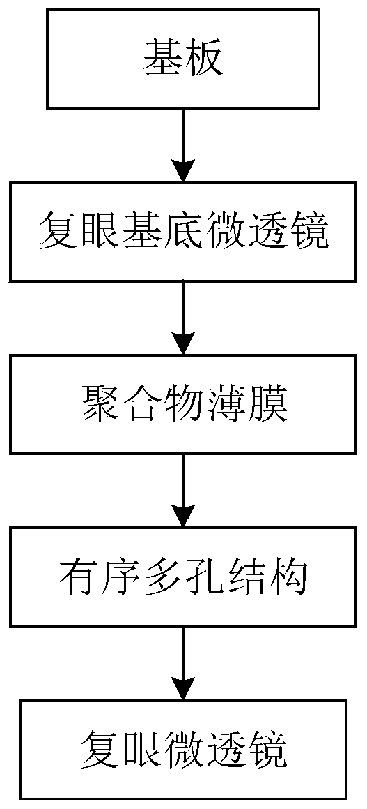
[0041] Such as figure 1 As shown, the present invention proposes a preparation method of a fly-eye microlens array, which is characterized in that the preparation method comprises the following steps:

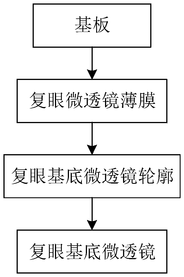
[0042] (a) On a clean substrate, use photoresist hot-melt method, nanoimprint method, photolithography method, ion beam etching method, electrospray printing method or static breath pattern method to prepare compound eye base microlens array, the compound eye base microlens array The diameter of the lens array is preferably 200 μm to 400 μm, and the crown height is preferably 40 μm to 150 μm;

[0043] More specifically, when preparing a single fly-eye microlens, it is only necessary to prepare a single fly-eye base microlens on a clean substrate, and when preparing a fly-eye microlens array, it is necessary to prepare a fly-eye base microlens array on a clean substrate;

[0044] (b) Dissolve the polymer in a volatile solvent, configure a polymer solution with a concentration o...

Embodiment 1

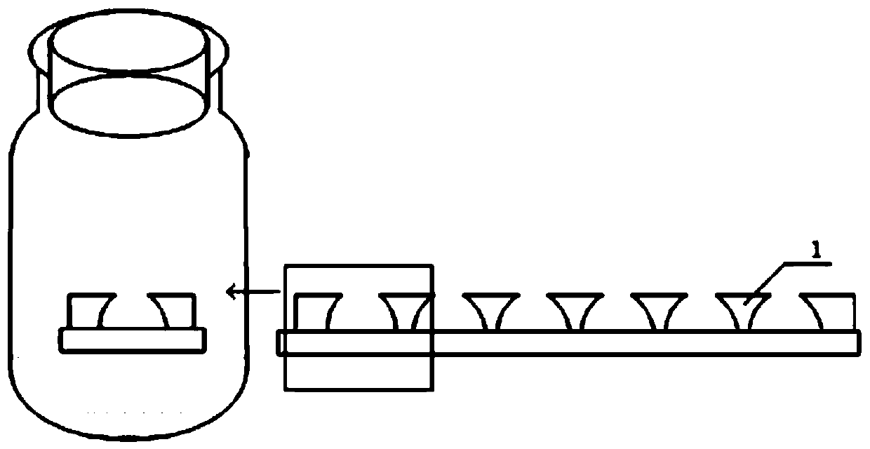
[0070] Such as Figure 3-7 As shown, the steps of preparing a curved surface fly-eye microlens array include:

[0071] (a) Fabrication of compound eye base microlens arrays by using the static breathing pattern method:

[0072] First, take a certain amount of polystyrene (PS) and place it in a volumetric flask, add a certain amount of toluene, seal it and dissolve it through ultrasonic vibration, and configure it into a PS toluene solution with a mass concentration of 25 mg / mL. 200 μL of PS toluene solution was evenly spin-coated on a 2cm×2cm substrate;

[0073] Then add 2mL of distilled water to a 25mL straight glass bottle equipped with a stopper, put a plastic support into the glass bottle, seal it with a stopper until the water vapor in the bottle reaches a humidity of 70%, place the substrate on the support, and make the substrate 1cm higher than the water level, then cover the plug and seal it, and let it stand at 25°C for 30s. After the toluene is completely volatiliz...

Embodiment 2

[0080] Utilize the method for step (a)~(c) in embodiment 1 to make the compound eye base microlens array with honeycomb ordered porous structure, then use Figure 8 A fly-eye microlens with a larger aspect ratio is prepared by using the wettability difference method as shown:

[0081] On the surface of the compound eye substrate microlens array with a honeycomb ordered porous structure, spin-coat a suspension of silica nanoparticles with a concentration of 4.2g / L, and control the thickness of the spin-coated silicon nanoparticles 6 to about 250nm. The particle 6 has a diameter of about 14nm, forming a surface with discontinuous wettability; then the substrate is put into the microlens solution 7, and then the substrate is pulled out, and the solution self-assembles to form a compound eye microlens 8 with a crown height of about 1.5 μm, and finally obtains the compound eye microlens array.


PUM

PropertyMeasurementUnit
diameteraaaaaaaaaa
concentrationaaaaaaaaaa
diameteraaaaaaaaaa

Abstract

The invention belongs to the field of compound eye micro-lenses and discloses a compound eye micro-lens array and a preparation method thereof, the preparation method comprises the following steps: preparing a compound eye substrate micro-lens array on a clean substrate; then dissolving the polymer in a volatile solvent to prepare a polymer solution, pouring the polymer solution on a substrate with a compound eye substrate microlens array, and forming a layer of uniform polymer film through spin coating; and placing the substrate in a closed container and standing for a period of time, obtaining a three-dimensional honeycomb-shaped ordered porous structure on the surface of the compound eye substrate microlens array after the solvent is completely volatilized, and preparing the compound eye microlens and further to make the compound eye microlens array. According to the invention, rapid and low-cost preparation of the compound eye microlens array can be achieved, and the high controllability of the shape, the diameter and the crown height of the bionic compound eye can be met.

Description

technical field [0001] The invention belongs to the field of fly-eye microlenses, and more specifically relates to a fly-eye microlens array and a preparation method thereof. Background technique [0002] In recent years, the compound eye structure of insects such as flies and moths has inspired researchers to design multi-scale microlenses. Each insect compound eye is composed of thousands to tens of thousands of small eyes. It is small in size, high in sensitivity, can measure speed, has almost 360° observation angle and high-precision resolution ability, and can be applied to cameras, military radar detectors, and precision guidance. , infrared detection and other vision systems and lighting systems have extremely broad application prospects in national defense, medical and commercial fields. The bionic compound eye structure is applied to optoelectronic devices such as OLEDs, which has the advantages of being able to achieve a large field of view and improve light extra...

Claims


Application Information

Patent Timeline
Patent Type & Authority Patents(China)
IPC IPC(8): G02B3/00
CPCG02B3/0006G02B3/0012G02B3/0056
Inventor 段永青黄永安王琪璐李华阳尹周平
Owner HUAZHONG UNIV OF SCI & TECH
Learn More