
Miniature diaphragm type optical fiber end FP pressure sensor, manufacturing method and application

A pressure sensor and optical fiber end technology, applied in the field of hydrogen-oxygen catalytic bonding solution configuration, can solve the problems of reducing sensor sensitivity, limiting sensor application, and low positioning accuracy, achieving high sensitivity and response bandwidth, expanding the scope of application, The effect of improving the service life

Active Publication Date: 2019-11-22
DALIAN UNIV OF TECH
View PDF9 Cites 7 Cited by
  • Summary
  • Abstract
  • Description
  • Claims
  • Application Information

AI Technical Summary

Problems solved by technology

However, the above solutions have disadvantages such as poor thermal stability, low positioning accuracy, and low efficiency, which greatly limit the application space, production efficiency, and service life of diaphragm sensors.
It is relatively simple to use organic glue such as epoxy resin to bond and fix the pressure-sensitive diaphragm to make the sensor. However, organic glue such as epoxy resin is not resistant to high temperature, and it is prone to creep under long-term stress, which directly limits the sensor's ability to withstand high temperature and high pressure transmission. Sensitivity and long-term monitoring applications, such as non-patent literature 1 ("High-sensitivity, high-frequency extrinsic Fabry-Perot interferometric fiber-tipsensor based on a thin silver diaphragm", Optics letters, 2012,37(9):1505 -1507.) described in
In Non-Patent Document 2 (“Adhesive-free bonding homogenous fused-silica Fabry-Perot optical fiber low pressure sensor in harsh environments by CO 2 laser welding”, Optics Communications, 2019, 435:97-101.) and 3 (“All-fused-silica miniature optical fiber tip pressure sensor”, Optics letters, 2006, 31(7):885-887.), laser Thermal fusion and arc welding are both welding methods based on thermal effects. These two solutions not only have low efficiency, but also require thicker and larger diameter diaphragms to ensure the success rate, which will reduce the sensitivity of the sensor and cause the volume to be too large
As described in Non-Patent Document 4 (“A highly sensitive fiber-optic microphone based on graphene oxidemembrane. Journal of Lightwave Technology”, 2017,35(19):4344-4349), direct bonding mainly relies on van der Waals force or hydrogen key to assemble the fiber optic sensor, does not provide sufficient structural strength and long-term stability
In Non-Patent Document 5 (“Miniature all-silica optical fiber pressure sensor with anultrathin uniform diaphragm”, Optics Express, 2010, 18(9):9006-9014), thermal bonding is a bond that can provide high strength However, high-temperature tools (such as a propane torch) are required to make the two interfaces to be bonded reach a molten state at the same time, which will lead to low alignment efficiency between the diaphragm and the hollow tube, and cannot achieve high-precision bonding positioning, making the diaphragm’s alignment The size is too large, resulting in a bulky sensor
Another example is described in Non-Patent Document 6 ("A novel MEMS pressure sensor fabricated on an optical fiber", IEEE Photonics Technology Letters, 2001, 13(9): 993-995.), for the anodic bonding method, in order to achieve high bonding Strength, usually need to apply high voltage on the interface to be bonded, high voltage device is required, it is difficult to achieve accurate positioning and assembly of micro-sized diaphragm devices

Method used


Image

  • Miniature diaphragm type optical fiber end FP pressure sensor, manufacturing method and application
  • Miniature diaphragm type optical fiber end FP pressure sensor, manufacturing method and application
  • Miniature diaphragm type optical fiber end FP pressure sensor, manufacturing method and application

Examples


Embodiment 1

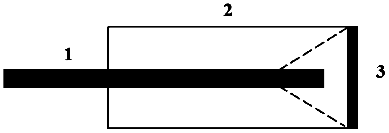
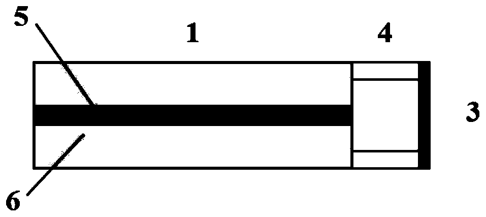
[0045] In the present invention, a single-mode optical fiber-hollow optical fiber-silica diaphragm constitutes a double-beam interference structure, and only uses arc welding and hydrogen-oxygen catalytic bonding to realize the overall all-quartz structure of the sensor. The sensor structure is as follows: figure 2 shown. Among them, the diameter of the single-mode fiber is 125 μm, and the core diameter is 9 μm; the outer diameter of the hollow-core fiber is 125 μm, and the inner diameter is 80 μm; the diameter of the silica diaphragm is 125 μm, and the thickness is 1 μm. The end face of the optical fiber and the inner surface of the silica diaphragm form two reflective surfaces, and the two reflected lights form a double-beam interference on the two surfaces, thus forming a low-precision FP interferometer. When the external pressure acts on the silicon dioxide diaphragm, the silicon dioxide diaphragm undergoes elastic deformation, causing the length of the FP interference ca...


PUM

PropertyMeasurementUnit
The inside diameter ofaaaaaaaaaa
Lengthaaaaaaaaaa
Thicknessaaaaaaaaaa

Abstract

The invention provides a miniature diaphragm type optical fiber end FP pressure sensor, a manufacturing method and application. The miniature diaphragm type optical fiber end FP pressure sensor includes an optical fiber, a hollow core optical fiber and a pressure-sensitive diaphragm, wherein the optical fiber and the hollow core optical fiber have the same diameters and the two are welded by arcs;and the pressure-sensitive diaphragm is bonded on the end surface of the hollow core optical fiber by using a hydrogen-oxygen catalytic bonding method. The entire quartz structure of the sensor can be realized, the existence of organic polymers at the joints of the elements is eliminated, and long-term stability and thermal stability are extremely high. The manufacturing method improves the applicable range and the service life of the sensor and the manufacturing cost is also reduced. The sensor provided in the invention can be applied to monitoring of parameters such as pressure and sound waves in extreme environments such as high temperature, high pressure, and strong corrosion, and can also be used for pressure measurement in the case of limited human body space in the medical and clinical field.

Description

technical field [0001] The invention relates to a manufacturing method of a micro-membrane type optical fiber end Fabry-Perot (FP) pressure sensor, which mainly includes the arc welding of the sensor and the hydrogen-oxygen catalytic bonding assembly scheme, and the hydrogen-oxygen catalytic bonding solution. configuration method. Background technique [0002] Pressure sensors are widely used in industrial manufacturing, medical, aerospace and other fields. The pressure sensor made of optical fiber has high application research value due to its small size, high sensitivity, anti-electromagnetic interference, and long-distance signal transmission. The main factor affecting the performance of optical fiber sensors is sensitivity, which is the key factor to determine whether the sensor can be practical. [0003] Fiber FP interferometer is an important model of fiber optic sensing. Its structure is divided into two types, one is intrinsic FP interference sensor, and the other...

Claims


Application Information

Patent Timeline
IPC IPC(8): G01L1/24G01L11/02
CPCG01L1/242G01L11/025G02B6/2551G01L9/0079G01L9/0077G02B6/2552
Inventor 荆振国彭伟刘悦莹刘强李昂
Owner DALIAN UNIV OF TECH
Learn More