Device and method for preparing magnesium oxide-based film with high secondary emission performance

An oxide film and thin film technology, applied in sputtering coating, vacuum evaporation coating, ion implantation coating and other directions, can solve the problems of poor resistance to electron/ion beam bombardment, unstable emission performance, limited composition control and so on , to achieve the effect of good secondary emission performance, stable secondary emission performance and adjustable composition

Inactive Publication Date: 2020-03-24
BEIJING UNIV OF TECH
View PDF6 Cites 2 Cited by
  • Summary
  • Abstract
  • Description
  • Claims
  • Application Information

AI Technical Summary

Problems solved by technology

[0005] For the single MgO film prepared by traditional radio frequency magnetron sputtering, the secondary electron emission performance is unstable, and the resistance to electron / ion beam bombardment is poor. Although the traditional silver-magnesium, copper-beryllium and other alloy-type secondary emission cathode materials are mature in technology, their composition Limited control and insufficient performance, the present invention adopts thermal evaporation combined with thermal activation (sensitization) technology, uses metals such as pure magnesium, aluminum, zinc, gold as evaporation source materials, and uses silicon wafers, quartz glass, FTO glass or silver, aluminum Conductive metal sheets are used as the substrate, and a single magnesium or aluminum film or magnesium-aluminum, magnesium-zinc, magnesium-gold alloy film is thermally evaporated under vacuum conditions, and then activated under low oxygen pressure to form magnesium oxide, aluminum oxide or Composite / doped MgO thin film

Method used


Image

  • Device and method for preparing magnesium oxide-based film with high secondary emission performance
  • Device and method for preparing magnesium oxide-based film with high secondary emission performance
  • Device and method for preparing magnesium oxide-based film with high secondary emission performance

Examples


Embodiment 1

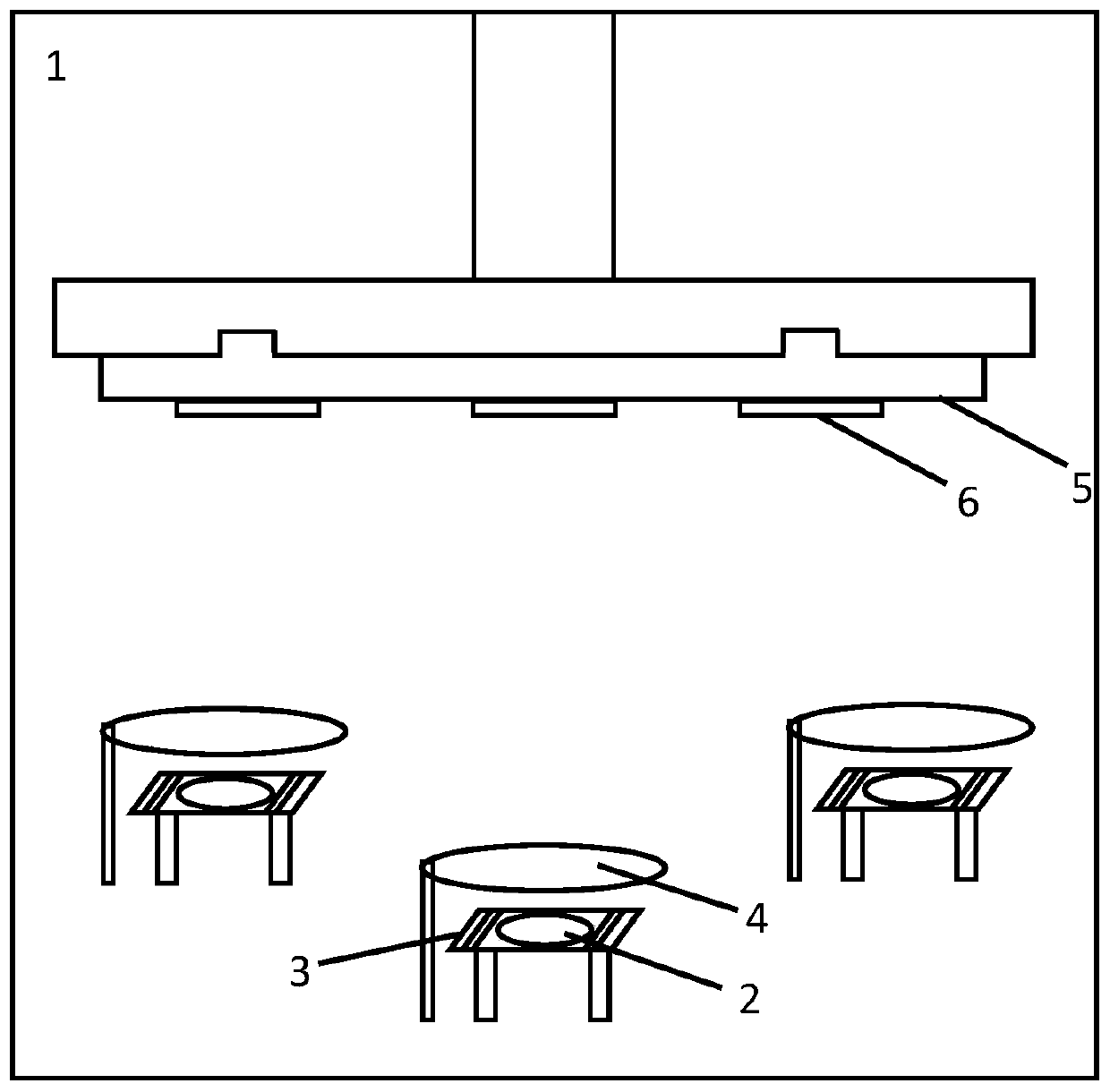
[0041] Weigh about 0.4g of high-purity magnesium particles, clean the surface according to the above method, and place it on the tungsten boat of the evaporation source in the vacuum chamber of the thermal evaporation apparatus. The tungsten boat is covered with a pure tungsten mesh. The flap above the tungsten boat remains closed. Adhere the cleaned FTO glass to the stainless steel substrate, and then place the substrate upside down on the sample holder. The vertical distance between the FTO glass to be evaporated and the evaporation source tungsten boat below it is 20 cm. Close the vacuum chamber door of the evaporation apparatus, and evacuate to 9.8×10 -4 Pa, turn on the evaporation power switch, adjust the current to 90A for 2min, and preheat the material to be evaporated. At the same time, the sample stage was turned on to rotate at 20 r / min. Increase the current to 110A, and open the flap above the tungsten boat, and stop loading the current after 2 minutes of thermal...

Embodiment 2

[0043] Weigh about 0.4g of high-purity magnesium particles, and clean the surface according to the above method. Weigh 0.4g of high-purity zinc wire, wind it into a roll, and place it and magnesium particles on two evaporation source tungsten boats in the vacuum chamber of the thermal evaporation apparatus, and cover the tungsten boats where the magnesium particles are located with pure tungsten mesh. The flaps above the two tungsten boats remain closed. Adhere the cleaned silicon wafer to the stainless steel substrate, and then place the substrate upside down on the sample holder. The vertical distance between the silicon wafer to be evaporated and the evaporation source tungsten boat below it is 20 cm. Close the vacuum chamber door of the evaporation apparatus, and evacuate to 9.8×10 -4 Pa, turn on the evaporation power switch, adjust the current to 90A for 2min, and preheat the material to be evaporated. At the same time, the sample stage was turned on to rotate at 20 r / ...

Embodiment 3

[0045] Weigh about 0.4g of high-purity magnesium particles, and clean the surface according to the above method. Weigh 0.4g of high-purity aluminum wire, polish the surface with 2000# sandpaper, clean it with ethanol, dry it with cold air, and wind it into a roll. Magnesium grains and aluminum wires are respectively placed on two evaporation source tungsten boats in the vacuum chamber of the thermal evaporation apparatus, and the tungsten boats where the magnesium grains are located are covered with pure tungsten mesh. The flaps above the two tungsten boats remain closed. Adhere the cleaned silicon wafer to the stainless steel substrate, and then place the substrate upside down on the sample holder. The vertical distance between the silicon wafer to be evaporated and the evaporation source tungsten boat below it is 20 cm. Close the vacuum chamber door of the evaporation apparatus, and evacuate to 9.8×10 -4 Pa, turn on the evaporation power switch, adjust the current to 90A ...


PUM


Abstract

The invention discloses a device and a method for preparing a magnesium oxide-based film with high secondary emission performance. The device comprises a thermal evaporation vacuum chamber, a thermalevaporation source substance, a tungsten boat and a substrate material which are arranged in the vacuum chamber, a vacuum tube furnace, and a gas flow controller, a fine tuning needle valve and oxygenwhich are matched with the vacuum tube furnace. A metal or alloy film is deposited on the surface of the substrate material through thermal evaporation, then trace oxygen is introduced into the vacuum tube furnace, the vacuum in the tube is kept at 5-100 Pa, the temperature is kept at 400-650 DEG C, thermal activation treatment is conducted, and a magnesium oxide-based film which is high in secondary emission coefficient and stable in emission is obtained, and the thickness of the thin film is about 100 nm to 1 [mu]m. The method is simple in process, adjustable in film structure and composition and stable in secondary emission performance, does not need to use an expensive ion source or an electronic gun, and is expected to be developed and applied to the fields of photoelectric multiples, image intensifiers, plasma flat-panel displays and the like.

Description

technical field [0001] The invention relates to a metal oxide functional thin film material and a preparation method thereof, in particular to a preparation method of a unit oxide or composite oxide thin film material with excellent secondary electron emission performance and stable operation, which belongs to the preparation of functional thin film materials technology field. Background technique [0002] Magnesium oxide is a wide bandgap semiconductor material with NaCl cubic crystal structure, which has good chemical inertness, high temperature resistance, electrical insulation, light transmission, and photocatalytic properties. Magnesium oxide is made into a thin film, which has a high secondary electron emission (or secondary emission) coefficient, and is the first choice for the secondary emission material of the electron multiplier in the photomultiplier tube and cesium atomic clock. In recent years, magnesium oxide thin films have been widely used in plasma flat pan...

Claims


Application Information

Patent Timeline
IPC IPC(8): C23C14/24C23C14/50C23C14/56C23C14/14C23C14/58
CPCC23C14/14C23C14/24C23C14/505C23C14/56C23C14/5853
Inventor 周帆梁轩铭王金淑邓琦键王蕊杨韵斐杨灏天李菲祺
Owner BEIJING UNIV OF TECH
Why Eureka
Try Eureka