
Stretchable microelectronic device taking hydrogel as substrate and preparation method

An electronic device and hydrogel technology, applied in the field of stretchable microelectronic devices, can solve problems such as insufficient mechanical strength and flexibility, difficulty in miniaturization of electrodes, and limitations on the application of flexible devices

Active Publication Date: 2020-04-07
SUN YAT SEN UNIV
View PDF5 Cites 21 Cited by
  • Summary
  • Abstract
  • Description
  • Claims
  • Application Information

AI Technical Summary

Problems solved by technology

However, due to the lack of mechanical strength and flexibility of traditional hydrogel materials, and weak adhesion with non-hydrophilic materials, it is difficult to implement the manufacturing technology of forming electrodes directly on the surface of hydrogels, and often requires additional flexible substrates as supports. Or a protective layer, increasing the complexity of the system and the instability of the gel-electrode-substrate interface
In addition, photolithography and other technologies used in traditional microelectronics are difficult to apply to the processing of flexible materials, and the miniaturization and patterning of electrodes also become difficult, which is easy to damage the hydrogel to a certain extent, and it is difficult to realize stretchable devices. , which will greatly limit the application of flexible devices based on hydrogel systems

Method used


Image

  • Stretchable microelectronic device taking hydrogel as substrate and preparation method
  • Stretchable microelectronic device taking hydrogel as substrate and preparation method
  • Stretchable microelectronic device taking hydrogel as substrate and preparation method

Examples


Embodiment 1

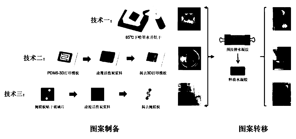
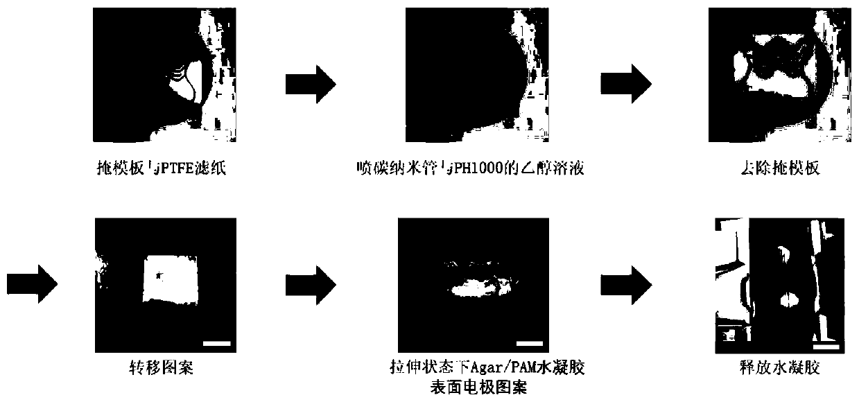
[0031] Transfer-printed carbon nanotube / conducting polymer composite electrode using PTFE filter paper substrate. The method follows image 3 The following steps are shown:

[0032] (1) Customize a stainless steel mask with a specific pattern, and the shape of the electrode ink leaked from the hollow part is the shape of the final micro-electrode.

[0033] (2) Attach the stainless steel mask plate to the PTFE filter paper and place it on a hot stage at 80°C.

[0034] (3) Prepare 0.2-2mg / mL carboxylated multi-walled carbon nanotubes (MWCNT) and 0.2-2mg / mL poly(3,4□ethylenedioxythiophene):polybenzenesulfonate (PEDOT:PSS) in ethanol solution. By diluting PH1000 (1.3-1.5%wt PEDOT:PSS aqueous solution), control the mass ratio of MWCNT and PEDOT:PSS between 1:5 and 5:1, and sonicate for 1h.

[0035] (4) Spray the prepared solution on the PTFE filter paper with a spray can, quickly remove the mask plate, and dry the electrode pattern on the filter paper at 80°C.

[0036] (5) Pre...

Embodiment 2

[0040] Activated carbon microelectrodes were transferred and printed using 3D printing templates and PDMS substrates. The method follows figure 2 The following steps are shown:

[0041] (1) Use 3D drawing software to establish the required electrode digital model with a certain shape, print out a single-layer polylactic acid (PLA) micro-pattern template with a precision of 500 microns, and the shape of the electrode slurry leaked from the hollow part is the final The shape of the microelectrodes.

[0042] (2) Mix PDMS (sylgard 184) prepolymer and cross-linking agent at a mass ratio of 10:1 to 5:1, fully mix for 10 minutes, and perform air extraction treatment, and the viscous liquid to be mixed does not contain air bubbles at all Then, slowly pour it into the Petri dish.

[0043] (3) Place the printed 3D printing template flat on the surface of the PDMS prepolymer viscous liquid. Then the petri dish was placed in an oven at 80°C for 1 hour to solidify the PDMS, and it was t...

Embodiment 3

[0047] Microelectrodes were transfer printed using a glass substrate. The method follows Figure 4 The following steps are shown:

[0048] (1) Customize a stainless steel mask with a specific pattern, and the shape of the electrode paste leaked from the hollow part is the shape of the final micro-electrode.

[0049] (2) Stick the wetted stainless steel mask to the glass surface by capillary action.

[0050] (3) Spray the ethanol solution of MWCNT / PEDOT:PSS composite electrode on the glass surface, or prepare electrode slurry with activated carbon, acetylene black and polytetrafluoroethylene (PTFE) binder, and use isopropanol as solvent, and evenly coat Apply on the mask plate, remove the mask plate, and the remaining pattern is the required electrode pattern.

[0051] (4) Dry the glass sheet printed with the micropattern on a hot table at 120° C. for 30 minutes.

[0052] (5) Transfer the electrode pattern to the surface of the hydrogel according to the aforementioned metho...


PUM

PropertyMeasurementUnit
Wire resistanceaaaaaaaaaa
Capacitanceaaaaaaaaaa

Abstract

The invention provides a stretchable microelectronic device taking hydrogel as a substrate and a preparation method of the stretchable microelectronic device. The preparation method comprises: the step 1, obtaining an intermediate product with a preset electrode pattern; the step 2, pre-stretching the tough hydrogel, and fitting the pre-stretched hydrogel with the intermediate product in the step1 to transfer the electrode pattern to the surface of the hydrogel; and the step 3, slowly releasing the hydrogel to recover the hydrogel to an unstretched state, so as to obtain the stretchable microelectronic device taking the hydrogel as the substrate. According to the invention, 3D printing, a template printing technology, a transfer printing technology and the like are combined, a flexible polytetrafluoroethylene (PTFE) filter membrane, polydimethylsiloxane (PDMS) silicone rubber or glass and the like are used as intermediary materials and matched with specially-made electrode slurry, anda stretchable micro device can be obtained through rapid and convenient printing on the surface of a tough hydrogel electrolyte represented by agar / polyacrylamide (Aar / PAM) and the like. The preparedmicro device comprises a micro sensor, a micro super capacitor and the like.

Description

technical field [0001] The invention relates to the technical field of stretchable microelectronic devices, in particular to a stretchable microelectronic device based on hydrogel and a preparation method. Background technique [0002] In recent years, with the miniaturization of electronic devices and the development of new materials, flexible electronic devices that are soft and close to the body and changeable shapes have gradually become a research and application hotspot. Highlights the huge application potential. In order to develop flexible wearable devices that can fit snugly on the human body surface, it is necessary to allow the electronics to withstand large tensile strains (>100%). Such stretchable electronic devices are usually achieved using two strategies, one is to develop new stretchable electronic materials, the other is to design materials and device structures that can withstand tensile stress, or to improve stretchability by combining multiple strate...

Claims


Application Information

Patent Timeline
IPC IPC(8): H01G11/84H01G11/86H01G11/56H01G11/38G01L1/18G01L1/20G01K7/16
CPCH01G11/84H01G11/86H01G11/56H01G11/38G01L1/18G01L1/20G01K7/16Y02E60/13
Inventor 谢庄方绿叶蔡泽帆丁正卿张家诚
Owner SUN YAT SEN UNIV
Learn More