A high ammonia nitrogen autotrophic denitrification device

An autotrophic denitrification and high ammonia nitrogen technology, applied in biological treatment devices, chemical instruments and methods, water/sludge/sewage treatment, etc., can solve the problems of easy sludge loss, high cost of chemical treatment, and large consumption , to achieve the effect of reducing the loss of biomass, improving the efficiency of biotransformation and shortening the doubling time

Active Publication Date: 2021-10-26
ZHEJIANG OCEAN UNIV
View PDF11 Cites 0 Cited by
  • Summary
  • Abstract
  • Description
  • Claims
  • Application Information

AI Technical Summary

Problems solved by technology

[0003] For the treatment of high ammonia nitrogen wastewater, the most commonly used methods are physical chemical method and biological treatment method. The physical chemical method needs to consume a large amount of chemicals, the treatment cost is high, and it is easy to cause secondary pollution. Biological treatment The commonly used method is the whole autotrophic denitrification process. The whole autotrophic denitrification reaction process includes nitrosation reaction and anaerobic ammonium oxidation reaction. First, AOB converts ammonia nitrogen into nitrite nitrogen, and the process is carried out under aerobic conditions; then , AnAOB uses the converted nitrite nitrogen as the electron acceptor to convert the remaining ammonia nitrogen into nitrogen gas, and this process is completed under anaerobic conditions
Although the full autotrophic denitrification process can significantly reduce operating costs and reduce the emission of more greenhouse gas nitrous oxide compared with physical and chemical methods, there are still certain technical problems in this technology, such as the initial start-up of anaerobic ammonium oxidation. The medium sludge is easy to lose, which makes it difficult to improve the treatment capacity of the reactor

Method used


Image

  • A high ammonia nitrogen autotrophic denitrification device
  • A high ammonia nitrogen autotrophic denitrification device
  • A high ammonia nitrogen autotrophic denitrification device

Examples


Embodiment 1

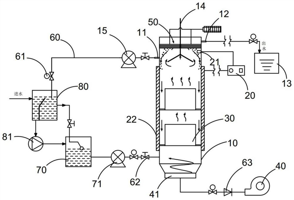
[0033] see Figure 1-7 As shown, a high ammonia nitrogen autotrophic denitrification device, including:

[0034] The reactor main body 10, the reactor main body 10 is a columnar structure, the bottom of which is connected to the third pump body 40 for aeration through the delivery pipe body 60, and the third pump body 40 is connected to the delivery pipe body 60 at the bottom of the reactor main body 10 A flow meter 61 and a check valve 63 are provided. The reactor main body 10 is made of plexiglass. The flow meter 61 is used to count the input oxygen flow, and the check valve 63 is set to prevent the backflow of oxygen or water. The oxygen supply mode is intermittent aeration mode, which is used to inhibit NOB (nitrite oxidizing bacteria). The whole process is carried out under micro-aerobic conditions. The ammonium oxidizing bacteria provide a substrate and provide an anaerobic environment to inhibit the growth of NOB. The reactor main body 10 used in this embodiment is a p...

Embodiment 2

[0049] The difference from Example 1 is:

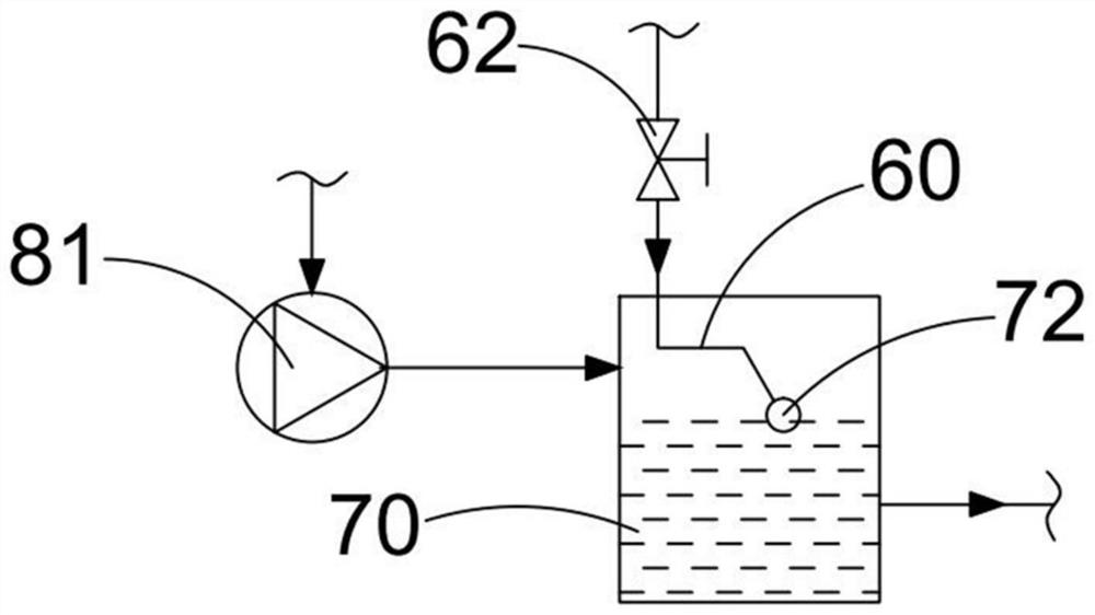
[0050] See attached Figure 7 , the delivery pipe body 60 that the return pipe 11 is connected with the pretreatment box 80 is provided with a denitrification treatment box 82, and denitrification bacteria are cultivated in the denitrification treatment box 82. A small amount of nitrate will be produced during the anaerobic ammonium oxidation reaction process, and the total TN concentration of the effluent can be further reduced through the reflux treatment process and the denitrification treatment tank 82, so as to improve the denitrification efficiency of the system, and an electric heater is installed in the water inlet tank 70 90. It is used to heat the water body. The cultured microorganisms have different active reactions at different water temperatures. In order to treat sewage with different water temperatures, the electric heater 90 is used to control the temperature of the water entering the reactor main body 10 to ensure th...

Embodiment 3

[0052] In this embodiment, a kind of high ammonia nitrogen autotrophic denitrification device of embodiment 1 is used for sewage treatment operation, as follows:

[0053] Inoculated sludge: The sludge inoculated in the reactor main body 10 is nitrosation (flocculent) sludge and anaerobic ammonium oxidation (granular) sludge. In the middle stage of the reactor start-up, the secondary sludge of the traditional urban sewage treatment plant is added to the reactor. Activated sludge in sedimentation tanks.

[0054] Wastewater treatment: the quality of influent water is wastewater with high ammonia nitrogen and low carbon to nitrogen ratio, such as sludge dehydration liquid of urban sewage treatment plants. An external temperature controller is connected with the heating jacket 22 to assist in controlling the water temperature.

[0055] The whole reaction process is avoided to run, specifically, black light-shielding material is used for shielding, and sampling tubes are used for s...


PUM

PropertyMeasurementUnit
heightaaaaaaaaaa

Abstract

The invention discloses a high-ammonia-nitrogen autotrophic denitrification device, which belongs to the technical field of wastewater treatment. The device includes a reactor main body, the bottom of which is connected to a third pump body through a delivery pipe body, and a three-phase separator, which is arranged in the upper part of the reactor main body , the bottom side wall of the reactor main body is connected with the second pump body through the conveying pipe body, the filler filling assembly is arranged in the reactor main body, and the ultrasonic processing assembly is arranged above the three-phase separator, and the ultrasonic processing assembly includes a hollow fiber membrane, a hollow fiber There is a superoxide combination pipe body above the membrane, and the superoxide combination pipe body is connected to the superoxide assembly respectively. The superoxide assembly is composed of a low-frequency ultrasonic vibrator and an air pump. The loss of the medium shortens the initial start-up time, realizes the microcirculation flow of the internal medium, improves the mass transfer effect, and ensures the stable operation of the denitrification process.

Description

technical field [0001] The invention belongs to the technical field of wastewater treatment, and in particular relates to a high ammonia nitrogen autotrophic denitrification device. Background technique [0002] Water is the source of life and the basic element for human survival. It maintains human survival, guarantees human production, and continues human development. China has a total of 2.81×10 fresh water 12 m 3 , of which surface water is 2.7×10 12 m 3 , groundwater 0.88×10 12 m 3 , is the sixth largest country with fresh water, but the per capita fresh water is only 25% of the world average. In addition, the uneven distribution of water resources in space and time in my country also makes the current situation of water resources more severe. With the increase of agricultural, industrial and domestic water consumption, the lack of water resources will greatly restrict the development of my country. Due to nitrogen pollution, water bodies The frequent occurrence o...

Claims


Application Information

Patent Timeline
Patent Type & Authority Patents(China)
IPC IPC(8): C02F3/30C02F101/16
CPCC02F3/301C02F3/303C02F3/307C02F2101/16C02F2203/004C02F2203/006
Inventor 阳广凤唐思敏刘亚雷穆军孙静亚冯丽娟杨桥张晓玲
Owner ZHEJIANG OCEAN UNIV
Why Eureka
Try Eureka