A system for in-situ electrocatalytic molten salt electrolysis synthesis of silicon nanofibers by diaphragm method
A molten salt electrolysis and silicon nanotechnology, applied in diaphragms, electrolysis components, electrolysis processes, etc., can solve the problems of difficulty in obtaining high-purity silicon nanofibers, difficulty in controlling the growth of silicon nanofibers, and reducing the purity of nanofibers, and achieve production costs. Low, easy to industrialize production, high conversion rate
- Summary
- Abstract
- Description
- Claims
- Application Information
AI Technical Summary
Problems solved by technology
Method used
Image
Examples
Embodiment 1
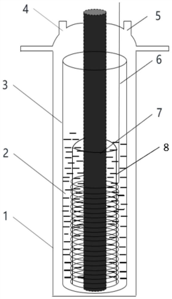
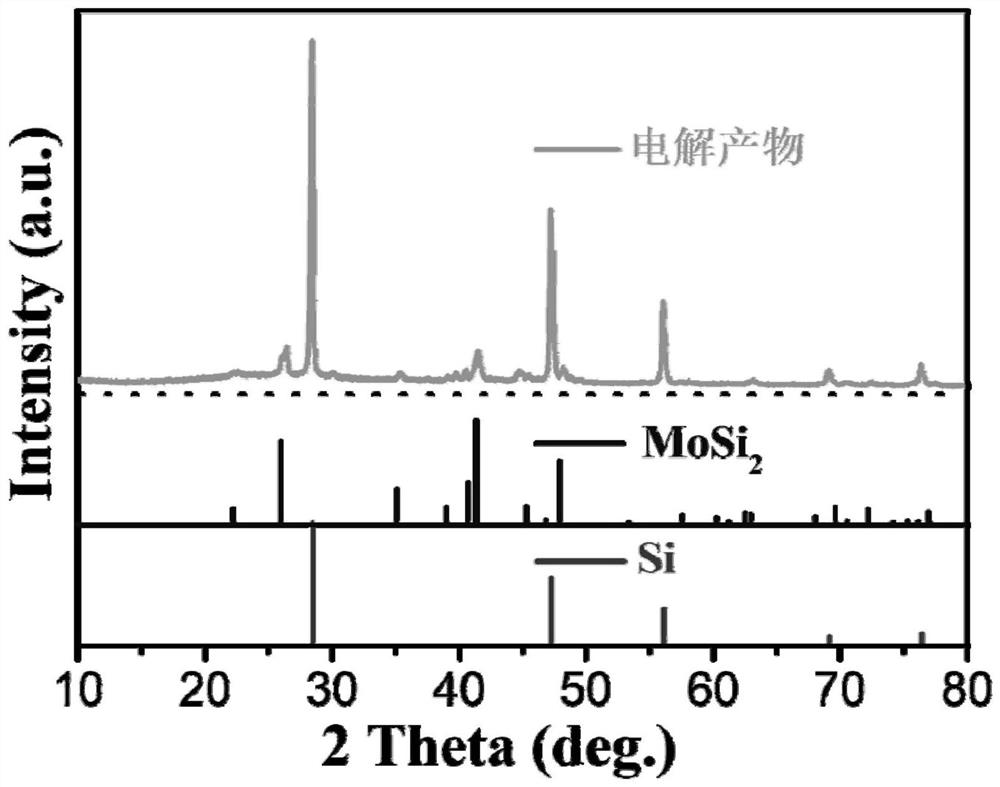
[0025] refer to figure 1 ,Such as figure 1 It is a system in which molybdenum in situ catalyzes and electrochemically generates controllable silicon nanofibers. The anode is a spiral molybdenum electrode 7, the cathode is a graphite electrode 6, and the composition of the diaphragm 8 is 0.94Al 2 o 3 0.02CaO 0.03SiO 2 0.01MgO, the pore size is 0.8-1.0μm, the porosity is 38%, the molten salt electrolyte is CaCl 2 , the precursor silicon source is 2.0wt% CaSiO 3 , the electrolysis temperature is 900°C, and the electrode distance is 2cm. The electrolyte CaCl 2 and precursor CaSiO 3 Under the protective atmosphere of fluid argon, heat up to 900°C at 5°C / min and hold for 1h, the initial voltage U 1 = Pre-electrolysis t at 2V 1 = 10 min. U is then applied between the cathode and anode 2 = 2.2V constant voltage electrolysis, electrolysis time t 2 = 4h. After the electrolysis, the product obtained at the cathode is washed and dried with dilute hydrochloric acid and deionize...
Embodiment 2-8
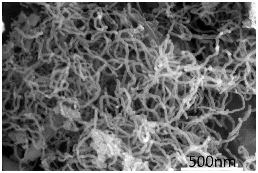
[0027] According to the method of embodiment 1, the molten salt electrolyte CaCl in 1 in the embodiment 2 Adjust the composition and replace it with NaCl+CaCl 2 (molar ratio 1:1), the melting point of the molten salt is reduced, and the electrolysis temperature is reduced to 800°C, and all the other parameters are consistent with Example 1. After the electrolysis, the obtained product was washed and dried. The electrolysis product obtained at the cathode undergoes such as Figure 4 According to SEM characterization, the obtained product is a silicon nanofiber with a diameter of about 15 nm.
[0028] After the molten salt composition of the electrolyte in Example 1 was adjusted, the electrolysis temperature changed accordingly. Other process parameters are the same as in Example 1, and the results are as shown in Table 1.
[0029]Table 1 Effect of molten salt composition on the synthesis of silicon nanofibers
[0030]
[0031]
[0032] Adjusting the composition of th...
Embodiment 9-14
[0034] According to the method for embodiment 1, change the electrolysis time t in 1 in the embodiment 1 and t 2 , voltage U 1 and U 2 After the electrolysis, the obtained product was washed and dried, and the morphology of the product was characterized by SEM, and the current efficiency and the proportion of silicon nanofibers were calculated. The results are shown in Table 2.
[0035] Table 2 Effect of electrolysis time and electrolysis voltage on Heheng silicon nanofibers
[0036] Example t 1 / min
[0037] The results in Table 2 represent the electrolysis time t 2 The longer the silicon nanofiber, the coarser the size of the nanofiber, the lower the purity of the nanofiber, and the lower the current efficiency; when it is lower than the minimum decomposition voltage of the molten salt component, the electrolysis voltage U 2 The larger the Si nanofibers obtained, the thicker the t 2 and U 2 is the main factor to regulate the size and length of silicon nan...
PUM
| Property | Measurement | Unit |
|---|---|---|
| pore size | aaaaa | aaaaa |
| diameter | aaaaa | aaaaa |
| diameter | aaaaa | aaaaa |
Abstract
Description
Claims
Application Information
 - R&D
- Intellectual Property
- Life Sciences
- Materials
- Tech Scout
- Unparalleled Data Quality
- Higher Quality Content
- 60% Fewer Hallucinations
Browse by: Latest US Patents, China's latest patents, Technical Efficacy Thesaurus, Application Domain, Technology Topic, Popular Technical Reports.
© 2025 PatSnap. All rights reserved.Legal|Privacy policy|Modern Slavery Act Transparency Statement|Sitemap|About US| Contact US: help@patsnap.com


