Method for recovering tail gas of gas-phase polyethylene device

A recovery method and polyethylene technology, applied in the field of VOCs recovery, can solve the problems of high ethylene recovery rate, sensitive gas composition changes, low investment cost, etc., and achieve high ethylene recovery rate, high equipment reliability, and low equipment investment. Effect

Active Publication Date: 2021-01-05
DALIAN UNIV OF TECH PANJIN INST OF IND TECH +1
View PDF7 Cites 2 Cited by
  • Summary
  • Abstract
  • Description
  • Claims
  • Application Information

AI Technical Summary

Problems solved by technology

However, there are disadvantages such as high investment cost, many moving equipment, and the operation of the system is sensitive to changes in gas components. Generally, it needs to be implemented together with the membrane sep...

Method used


Image

  • Method for recovering tail gas of gas-phase polyethylene device
  • Method for recovering tail gas of gas-phase polyethylene device
  • Method for recovering tail gas of gas-phase polyethylene device

Examples


Embodiment 1

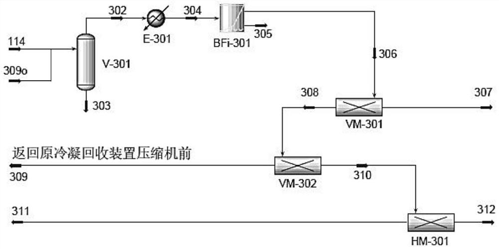
[0035] The schematic diagram of the technological process of this embodiment is as image 3 Show. The exhaust gas 114 from the typical process flow of the gas phase polyethylene process exhaust gas recovery unit first enters the buffer tank V-301, and the liquid mist entrained in the exhaust gas is separated by gravity sedimentation and wire mesh capture. The oil accumulated at the bottom of the tank is discharged regularly through the switch valve at the bottom of the tank. The polymerization tail gas is extracted from the top of the tank, and enters the raw material preheater E-301 to increase the temperature (the operating temperature range of the membrane module is 10-40°C, and the preset temperature is 20°C) to avoid damage to the separation layer of the membrane module by condensation of light hydrocarbons. The heated polymerization tail gas then enters the coalescing filter BFi-301 to further remove fine particles that may damage the membrane modules. Particles and ga...

Embodiment 2

[0045] The organic vapor membrane is a rubbery gas separation membrane, and its preparation method is:

[0046] Step 1: Under the protection of nitrogen, 100kg of vinyl polytrifluoropropylmethylsiloxane and 1300kg of ethyl acetate were stirred at 37°C for 6h, then 19kg of tetramethyl(hydrogen)disiloxane and 4kg of tetramethyl(hydrogen)disiloxane were added. Platinum-based catalyst, 0.2 kg of 1-vinyl-3-butylimidazole bistrifluoromethanesulfonimide salt, 1.9 kg of vinyl phenyl sulfone, stirred at 72° C. for 160 min to obtain a coating solution.

[0047] Step 2, soak 50kgPEI hollow fiber base membrane in 1700kg deionized water, soak at room temperature for 4h, remove and dry, then immerse it in 1500kg coating solution and coat it for 70min; take out the composite membrane coated with coating solution and place In the fume hood, after the ethyl acetate was fully volatilized, the composite membrane was placed in a blast drying oven at 86°C for 4 hours to obtain a rubbery gas separa...

Embodiment 3

[0050] The organic vapor membrane is a rubbery gas separation membrane, and its preparation method is:

[0051] Step 1: Under nitrogen protection, stir 100kg of vinyl polytrifluoropropylmethylsiloxane and 2000kg of ethyl acetate at 50°C for 10h, then add 23kg of tetramethyl(hydrogen)disiloxane and 5kg of Platinum-based catalyst, 0.6 kg of 1-vinyl-3-butylimidazole bistrifluoromethanesulfonimide salt, 3.9 kg of vinyl phenyl sulfone, stirred at 75° C. for 180 min to obtain a coating solution.

[0052] Step 2, soak 50kgPEI hollow fiber base membrane in 2000kg deionized water, soak at room temperature for 5h, remove and dry, then immerse it in 2000kg coating solution and coat it for 100min; take out the composite membrane coated with coating solution and place In the fume hood, after the ethyl acetate was fully volatilized, the composite membrane was placed in a blast drying oven at 90°C for 6 hours to obtain a rubbery gas separation membrane. Others are with embodiment 1.

[005...


PUM


Abstract

The invention belongs to the technical field of VOCs recovery, and particularly relates to a method for recovering tail gas of a gas-phase polyethylene device. In a typical process of an exhaust gas recovery unit of a gas-phase polyethylene process, under the limitation of compression capacity and condensation temperature, a part of hydrocarbon gas still cannot be recycled and is directly discharged to a torch system, so that raw material waste and discharge pollution are caused. At present, an exhaust gas recovery system is modified by a part of built gas-phase polyethylene devices in China,common recovery technologies include membrane separation, cryogenic treatment, membrane and cryogenic treatment combination and the like, but the characteristics of high ethylene recovery rate, low investment cost and the like cannot be considered at the same time. The invention provides the method for recovering tail gas of a gas-phase polyethylene device, which not only can meet the recovery requirements of C4 <+> hydrocarbons, but also has the advantages of high ethylene recovery rate, lower investment cost, less dynamic equipment and the like.

Description

technical field [0001] The invention belongs to the technical field of VOCs recovery, and in particular relates to a method for recovering tail gas from a gas-phase method polyethylene plant. Background technique [0002] With the vigorous development of my country's ethylene industry, the use of ethylene to produce polyethylene products is the main direction of ethylene utilization. In recent years, the average annual growth rate of polyethylene demand has reached more than 6%. At present, my country is still building a large number of polyethylene production device. The gas-phase polymerization process occupies an important position in my country's polyethylene plant. The exhaust gas recovery unit is an important part of the gas-phase polyethylene process. It mainly recovers a large amount of unreacted hydrocarbons in the reaction system through traditional compression and condensation. similar substances to achieve the purpose of reducing material consumption, energy savin...

Claims


Application Information

Patent Timeline
IPC IPC(8): B01D53/22B01D50/00F23G7/06
CPCB01D53/229B01D53/228B01D53/226F23G7/06B01D2258/02B01D2256/24B01D2256/10B01D50/20
Inventor 代岩贺高红阮雪华郭明钢
Owner DALIAN UNIV OF TECH PANJIN INST OF IND TECH
Why Eureka
Try Eureka