Cu3P@P-doped mesoporous carbon composite framework, and preparation method and application thereof

A mesoporous carbon skeleton and mesoporous carbon technology, applied in the direction of electrode carriers/current collectors, active material electrodes, electrical components, etc., can solve the problems of low Coulombic efficiency, uncontrollable dendrites, large volume effect, etc., and achieve accelerated transmission , reduce negative effects, and accelerate the effect of catalytic conversion

Active Publication Date: 2021-10-08
CENT SOUTH UNIV
View PDF10 Cites 1 Cited by
  • Summary
  • Abstract
  • Description
  • Claims
  • Application Information

AI Technical Summary

Problems solved by technology

The present invention provides a Cu3P@P-doped mesoporous carbon composite framework material (also called Lithophilic Composite Mesoporous Carbon, or Lithophilic Mesoporous Carbon for short), aims to pass stable Cu3P nanoparticles selectively induces the uniform deposition of lithium in the inner cavity of the carbon framework, improves the uneven deposition of lithium under high current, reduces the volume effect, and improves the lithium metal anode. cycle performance

Method used


Image

  • Cu3P@P-doped mesoporous carbon composite framework, and preparation method and application thereof
  • Cu3P@P-doped mesoporous carbon composite framework, and preparation method and application thereof
  • Cu3P@P-doped mesoporous carbon composite framework, and preparation method and application thereof

Examples


Embodiment 1

[0065] SiO with an average particle size of 200 nm 2 The balls were prepared into a 10g / L sol, stirred evenly at 50°C, then added cassava flour, and stirred vigorously. Cassava flour, SiO 2 The weight ratio is 50:40. Stir for 3h and dry for 12h. Transfer to a tube furnace under argon flow, heat up to 1000°C at a rate of 5°C / min and roast for 3 hours, after cooling down, place in 5M NaOH solution and stir for 12 hours, filter and wash, and dry at 80°C for 8 hours to prepare mesoporous carbon.

[0066] Get the mesoporous carbon that 0.5g above-mentioned steps prepares (specific surface area is 500m 2 / g, the carbon wall thickness is 30nm, and the chamber volume ratio is 70%) in 100ml of copper acetate ethanol solution with a concentration of 10g / L, magnetically stirred at 25°C for 12h, filtered, cleaned, and dried, in a tube furnace Under an argon atmosphere, the temperature was raised to 800 °C for 3 h at a rate of 5 °C / min to obtain CuO nanoparticles@mesoporous carbon.

...

Embodiment 2

[0071] SiO with an average particle size of 300 nm 2 The balls were formulated into 15g / L sol, stirred evenly at 50°C, then added sucrose, and stirred. Sucrose, SiO 2 The weight ratio is 55:45. The stirring time is 3h, and the drying time is 12h. Transfer to a tube furnace and heat up to 9000°C for 5 hours at a rate of 8°C / min under argon flow, then place in 6M NaOH solution and stir for 24 hours after cooling down, filter and wash, and dry at 80°C for 8 hours to prepare mesoporous carbon.

[0072] Get the mesoporous carbon that 0.5g above-mentioned steps prepares (specific surface area is 610m 2 / g, the carbon wall thickness is 25nm, and the chamber volume ratio is 75%) in 100ml of copper nitrate propanol solution with a concentration of 30g / L, magnetically stirred at 25°C for 8h, filtered, cleaned, dried, and dried in a tube furnace Under argon atmosphere, the temperature was raised to 900°C at a rate of 510°C / min and calcined for 2.5h to obtain Cu nanoparticles@mesoporo...

Embodiment 3

[0076] SiO with an average particle size of 300 nm 2 The balls were prepared into 10g / L sol, stirred at 50°C, and then starch was added and stirred. Starch, SiO 2 The weight ratio is 50:40. Stir for 3h and dry for 12h. Transfer to a tube furnace and heat up at 3°C / min to 1200°C for 2h under an argon flow. After cooling down, stir in 8M NaOH solution for 12h, filter and wash, and dry at 80°C for 8h to prepare mesoporous carbon.

[0077] Get the mesoporous carbon that 0.5g above-mentioned steps prepares (specific surface area is 600m 2 / g, the carbon wall thickness is 26nm, and the chamber volume ratio is 73%) in 100ml of copper acetate ethanol solution with a concentration of 40g / L, magnetically stirred at 30°C for 18h, filtered, cleaned, and dried, in a tube furnace Under an argon atmosphere, the temperature was raised from 5°C / min to 1000°C for 5h to obtain Cu nanoparticles@mesoporous carbon.

[0078] Take 3g of sodium metaphosphate and place it in the upper airflow dire...


PUM

PropertyMeasurementUnit
Specific surface areaaaaaaaaaaa
Particle sizeaaaaaaaaaa

Abstract

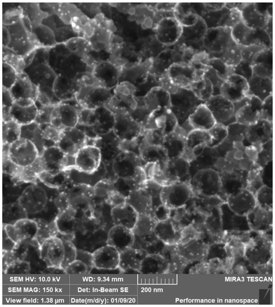
The invention belongs to the technical field of lithium metal battery materials, and particularly discloses a Cu3P@P-doped mesoporous carbon composite framework, and a preparation method and application thereof. The Cu3P@P-doped mesoporous carbon composite framework comprises thin-wall mesoporous carbon frameworks which are mutually crosslinked, cavities which are mutually communicated, Cu3P nanoparticles which are compounded on the inner sides of the cavities of the mesoporous carbon frameworks, and phosphorus-containing functional groups which are doped on the mesoporous carbon frameworks; a large number of cavities are contained in the mesoporous carbon frameworks, and the cavities are of a three-dimensional networked structure communicated through pore channels; the Cu3P nanoparticles are doped on the inner sides of the cavities of the mesoporous carbon frameworks in situ; and the phosphorus-containing functional groups are uniformly distributed on the surfaces of the mesoporous carbon frameworks. The Cu3P@P-doped mesoporous carbon composite framework material provided by the invention has a relatively large specific surface area, and can effectively reduce the local current density; due to the mutually communicated cavity structures, the transmission of lithium ions can be accelerated, and the reaction kinetics can be optimized; the Cu3P nanoparticles and the phosphorus-containing functional groups are used for inducing the deposition behavior of lithium, and selective deposition is realized; and the constructed lithium metal negative electrode has excellent electrochemical performance, and the coulombic efficiency and the cycling stability are greatly improved.

Description

technical field [0001] The invention belongs to the technical field of lithium metal battery electrode materials, and in particular relates to a current collector of a lithium metal battery and a preparation method and application thereof. Background technique [0002] Lithium metal has a very high mass-to-energy ratio, and is considered to be the most promising high-energy secondary energy storage device in the future for new energy vehicles and mobile electronic devices. However, due to the reaction mechanism of lithium metal anode dissolution / deposition, the electrode produces inevitable volume change and lithium dendrite growth, which greatly affects the electrochemical performance and safety of the battery, making it difficult to commercialize it. [0003] At present, the construction of a lithium-friendly 3D framework structure is considered to be an effective means to solve the volume effect and lithium dendrite growth. The 3D current collector or skeleton structure ...

Claims


Application Information

Patent Timeline
IPC IPC(8): H01M4/62H01M4/66H01M4/134H01M10/052
CPCH01M4/628H01M4/663H01M4/667H01M4/134H01M10/052H01M2004/021H01M2004/027Y02E60/10
Inventor 洪波赖延清姜怀范鑫铭张治安张凯方静
Owner CENT SOUTH UNIV
Why Eureka
Try Eureka