Controllable liquid flow-vibration coupling auxiliary laser milling and polishing machining method and system

An auxiliary laser and processing system technology, applied in laser welding equipment, metal processing equipment, manufacturing tools, etc., can solve problems such as rapid changes, plasma exhaustion effects, and affecting laser energy absorption, so as to avoid microcracks and improve discharge chip characteristics and processing quality, and the effect of improving removal efficiency

Active Publication Date: 2021-12-03
NINGBO INST OF MATERIALS TECH & ENG CHINESE ACADEMY OF SCI
View PDF9 Cites 4 Cited by
  • Summary
  • Abstract
  • Description
  • Claims
  • Application Information

AI Technical Summary

Problems solved by technology

However, laser processing will introduce problems such as heat-affected zones, recast layers, and microcracks. For hard and brittle materials, the laser thermal effect is likely to cause a sharp change in the internal stress of the material in the processing radiation area, and it is easy to induce the initiation and propagation of crack sources and damage the material. At the same time, the exhaustion effect of laser processing plasma affects the absorption of laser energy; and the adhesion of processing products, spatter or residues is easy to form a recast layer, which will affect the quality of the processed surface

Method used


Image

  • Controllable liquid flow-vibration coupling auxiliary laser milling and polishing machining method and system
  • Controllable liquid flow-vibration coupling auxiliary laser milling and polishing machining method and system
  • Controllable liquid flow-vibration coupling auxiliary laser milling and polishing machining method and system

Examples


Embodiment 1

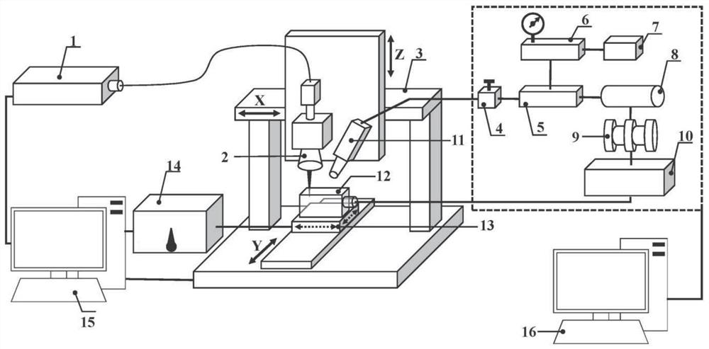
[0071] Example 1: See figure 1 , Which shows a controllable flow - vibrational coupling of laser assisted milling Polishing system, the processing system may also be designated as a controlled jet - vibration coupling aid milling Polishing laser system comprising a laser machining unit, stream auxiliary unit, the auxiliary vibrating unit, the motion control unit and the auxiliary unit.

[0072] Wherein the laser processing unit mainly includes cooperating fiber laser 1 and the laser processing head, the laser processing head 2 includes a scanning galvanometer, for a workpiece processing zone is provided in the laser processing.

[0073] Wherein, the exercise assisting unit 3 includes a motion platform, the workpiece may be provided on the moving platform 3, and the laser processing head 3 is also connected to the moving platform. The motion platform 3 at least drive the laser machining head and the workpiece in a three dimensional coordinate system in the X, Y, Z three directions ...

Embodiment 2

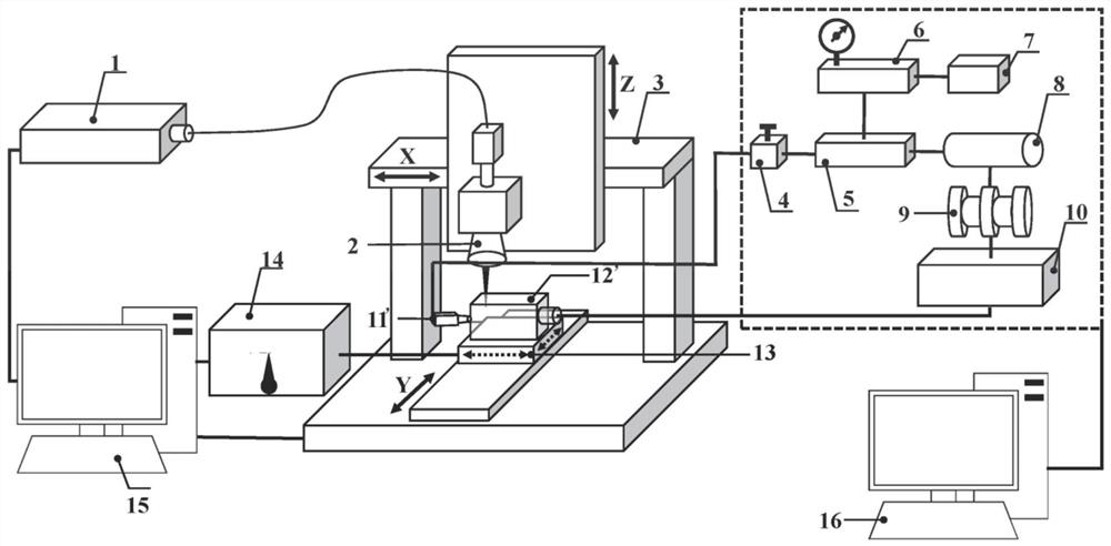
[0088] Example 2: See figure 2 , Shown therein a controlled flow - vibrational coupling of laser assisted milling Polishing system is substantially the same as in Example 1, with the difference that: wherein the auxiliary unit includes a stream flow rate control valve 4, a controller 5, the pressure sensor 6 , turbocharger 7, an accumulator 8, a pump 9, water tank 10, the flow channel controller 11 ', the closed auxiliary flow static process vessel 12' is provided in the flow line and between these devices and the like. Wherein, the water tank 10 for supplying water or other liquid. The outlet 10 of the water tank sequentially through the pump 9, an accumulator 8, the controller 5, a flow regulating valve 4, the flow channel controller 11 'of the closed auxiliary flow static process vessel 12' in communication. The closed auxiliary flow static process vessel 12 'may be provided in the processing area, and the workpiece 12 can be fixed to clamp the closed auxiliary flow static proc...


PUM


Abstract

The invention discloses a controllable liquid flow-vibration coupling auxiliary laser milling and polishing machining method and system. The machining system comprises a laser machining unit used for conducting laser machining on a workpiece; a liquid flow auxiliary unit used for providing liquid flow to be in contact with the workpiece; a vibration auxiliary unit used for applying vibration to the workpiece; and a control unit used for regulating and controlling the working states of the laser machining unit, the liquid flow auxiliary unit and the vibration auxiliary unit so as to realize controllable coupling of laser machining, vibration and liquid flow. By controllable coupling of laser, vibration, liquid flow and the like, superiority of each process/energy field can be exerted, coupling complementation is realized, macro-micro-scale energy distribution characteristics of a machining area are effectively regulated and controlled, heat influence is reduced, micro-cracks are avoided, laser milling and polishing chip removal characteristics and machining quality are remarkably improved, workpiece quality is greatly improved, and the material removal efficiency is effectively improved. The machining system of the invention is particularly suitable for precision machining of metal materials, hard and brittle materials and the like.

Description

Technical field [0001] The present invention relates to a laser processing method, and more particularly to a controlled liquid-vibration coupling auxiliary laser milling process, a realization device, which belongs to laser processing, multi-field fusion, and advanced manufacturing technology. Background technique [0002] Engineering ceramics such as "third generation material" after metal and plastic, according to chemical composition can be divided into metal oxides, nitrides, carbides, etc., have high strength, high hardness, anti-oxidation , Corrosion resistance, abrasion resistance, ablation, small density, good electrical insulation performance, etc., are widely used in aerospace, electronic, chemical machinery, biological engineering and other industries. When using machining methods such as turning, grinding, grinding, ultrasonic machining, electric spark and abrasive water jets, easy to produce surface defects such as tool wear, surface scratches, and residual stress, ...

Claims


Application Information

Patent Timeline
Patent Type & Authority Applications(China)
IPC IPC(8): B23K26/36B23K26/70B23K26/08B23K26/146
CPCB23K26/36B23K26/70B23K26/08B23K26/146
Inventor 陈晓晓张文武李源
Owner NINGBO INST OF MATERIALS TECH & ENG CHINESE ACADEMY OF SCI
Why Eureka
Try Eureka