Solar radio frequency spectrograph receiving system and method

A solar radio and receiving system technology, applied in the field of radio spectrum analyzers, can solve the problems of poor in-band clutter suppression, fundamental wave mixing local oscillator leakage, digital receiver damage, etc. The effect of large gain and reduction of transmission line loss differences

Active Publication Date: 2022-03-29
SHANDONG UNIV
View PDF8 Cites 0 Cited by
  • Summary
  • Abstract
  • Description
  • Claims
  • Application Information

AI Technical Summary

Problems solved by technology

There may be local oscillator leakage in the fundamental wave mixing frequency. At the same time, if the balanced frequency mixing structure is used, the in-band clutter suppression is not good, and the output high-order clutter may be just on the sideband of the output frequency and cannot be filtered by the output filter. If it is dropped, it will have a great impact on the performance of the receiver
The local oscillator signals generally required for subharmonic mixing are 4 or 8 equally spaced signals of the same frequency, and their frequency is half that of the RF carrier signal. In order to generate these different local oscillator signals, it is necessary to design a complex phase filter , increasing the design difficulty
At the same time, phase filter components are generally passive devices. The more phases, the more components, and the power consumption will increase significantly, which is contrary to the principle of low power consumption design.
[0004] Moreover, the dynamic range of the analog receiving system of the current main metric-wave solar radio spectrometer is fixed. When the solar radio burst is very strong, on the one hand, it may cause damage to the subsequent digital receiver, and on the other hand, it cannot perform well. Observations are not conducive to the subsequent description, analysis and application of solar radio bursts

Method used


Image

  • Solar radio frequency spectrograph receiving system and method
  • Solar radio frequency spectrograph receiving system and method
  • Solar radio frequency spectrograph receiving system and method

Examples


Embodiment 1

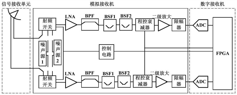
[0037] This embodiment provides a solar radio spectrum instrument receiving system, such as figure 1 As shown, it includes a signal receiving unit, an analog receiver and a digital receiver connected in sequence, and the signal receiving unit adopts an antenna system for receiving solar radio signals or other space electromagnetic signals.

[0038] Since the sun’s opening angle to the earth is only 0.5 degrees, in order to achieve high-precision collection of solar radiation electromagnetic signals and reduce interference from other signals, the antenna system needs to have good directivity. The antenna system of this embodiment includes an antenna with a diameter of 12 meters and a dual-linear polarization feed system. The antenna has a parabolic reflector, and the dual-linear polarization feed system is arranged at the focal point of the reflector.

[0039] The solar radiation electromagnetic signal is converged to the feed source system at the focal point through the reflec...

Embodiment 2

[0068] This embodiment provides a receiving method for a solar radio spectrum instrument. The system described in Embodiment 1 is adopted. Since the above-mentioned system processes the horizontal signal and the vertical signal of the antenna system in the same way, this embodiment takes the horizontal signal as an example. Instructions, the specific processing steps are as follows:

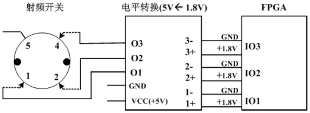
[0069] Step 1: The horizontal signal received by the antenna enters an analog channel through one end of the RF switch.

[0070] Step 2: In order to reduce the system noise figure, the horizontal input signal through the RF switch is first amplified by a low-noise amplifier (LNA).

[0071] Step 3: In order to ensure the frequency range of the input signal, the signal is filtered through a band-pass filter (BPF) with a frequency range of 90-600 MHz.

[0072] Step 4: In the field electromagnetic environment test of the observation station, it is found that there are frequent and relatively strong ...

Embodiment 3

[0083] In this embodiment, the signal receiving unit of the system described in Embodiment 1 is simulated and verified, as shown in Figure 4(a)-Figure 4(c), and the following conclusions are obtained:

[0084] (1) The antenna gain is high, not less than 17.1dBi, of which 90MHz: 17.1dBi; 200MHz: 23.9dBi; 400MHz: 29.9dBi; 600MHz: 33.3dBi.

[0085] (2) The beam is narrow.

[0086] The system gain of one channel of the analog receiver system is as follows: Figure 5 Shown, show that embodiment one is feasible, can be well used for receiving the solar radio signal of 90-600MHz, and carry out solar radio burst research.


PUM


Abstract

The invention discloses a solar radio frequency spectrograph receiving system and method, and relates to the technical field of radio frequency spectrographs, the solar radio frequency spectrograph receiving system comprises a signal receiving unit, an analog receiver and a digital receiver, the signal receiving unit is used for receiving solar radio signals and adopts a large-aperture paraboloid reflecting surface and a dual-linear polarization feed source; the analog receiver is used for processing two analog channels of solar radio signals, and each analog channel comprises a radio frequency switch, a primary amplifier, a band-pass filter, a band elimination filter, a programmable attenuator, a secondary amplifier and an amplitude limiter which are connected in sequence; the digital receiver comprises an FPGA (Field Programmable Gate Array) and a data acquisition card, the amplitude limiter is connected with the FPGA through the data acquisition card, the programmable attenuator is connected with the FPGA through a line, and the FPGA starts the programmable attenuator when judging that solar radio burst meets a set condition. According to the invention, the large-aperture antenna system is adopted to improve the receiving quality of solar radio signals; program-controlled attenuation is added to realize system dynamic gain and expand the dynamic range of the receiving system; a frequency mixing scheme is not needed, the structure is simple, and the cost is low.

Description

technical field [0001] The invention relates to the technical field of radio spectrum analyzers, in particular to a receiving system and method for solar radio spectrum analyzers. Background technique [0002] A solar radio spectrum analyzer usually consists of an antenna and an antenna feeder system, an analog receiver, a digital receiver, and a host computer (terminal device). The existing solar radio spectrum analyzer usually adopts a frequency mixing scheme. For example, a signal receiving device of a solar radio spectrum instrument includes an indoor unit, an outdoor extension unit and a transmission cable. The outdoor extension unit includes a microwave switch, a limiter, a filter, and a low-noise amplifier. and control circuits; the frequency mixing scheme has many channels, high cost, and it is difficult to match the consistency between channels. [0003] The commonly used mixer structures mainly include fundamental wave mixing and subharmonic mixing. There may be ...

Claims


Application Information

Patent Timeline
Patent Type & Authority Applications(China)
IPC IPC(8): H04B1/16H01Q15/16
CPCH04B1/16H01Q15/16
Inventor 常树旺路光申玉鹏白宇董镇尚自乾张磊王玉玺陈耀苏艳蕊武昭严发宝
Owner SHANDONG UNIV
Why Eureka
Try Eureka