

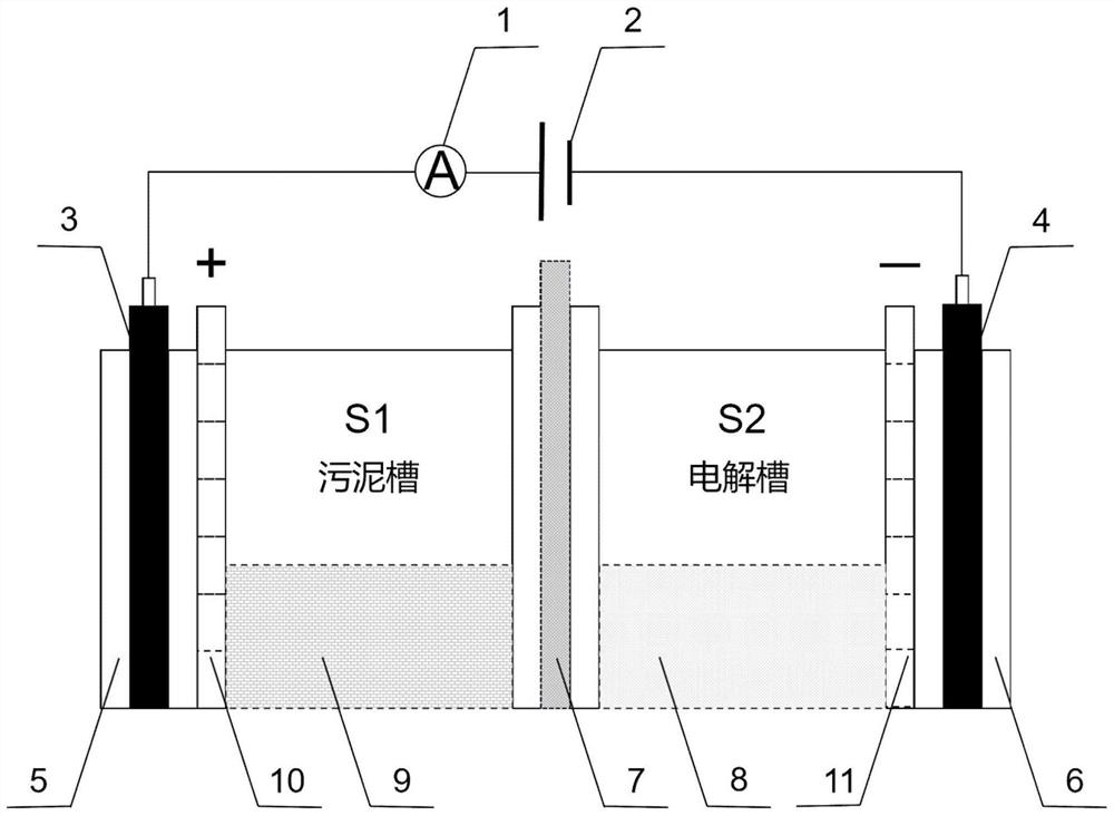
Device for removing heavy metal in sludge in situ through electric coupling of graphene hydrogel
A graphene hydrogel, heavy metal technology, applied in graphene, electrochemical sludge treatment, water/sludge/sewage treatment and other directions, to achieve the effect of improving electrical conductivity, improving adsorption effect, and reducing workload
- Summary
- Abstract
- Description
- Claims
- Application Information
AI Technical Summary
Problems solved by technology
Method used
Image

Examples
specific Embodiment approach
[0024] The technical solutions of the present invention are not limited to the specific embodiments listed below, but also include any combination of specific embodiments.
specific Embodiment approach 1
[0025] Embodiment 1: The process of removing the heavy metal in the sludge in the device for in-situ removal of heavy metals from sludge by electrokinetic coupling graphene hydrogel is carried out according to the following steps:
[0026] Step 1. Preparation of graphene oxide solution: prepare an ice-water bath, and in the water bath, pass the graphite powder of 200 mesh sieves and the mixed solution of concentrated sulfuric acid and concentrated phosphoric acid, wherein the volume ratio of sulfuric acid and phosphoric acid is 9:1, mixed. The liquid-solid mass ratio of the resulting solution and the graphite powder is 110:1, and the temperature is guaranteed to be below 10 °C, and the ice bath is stirred at a speed of 1000rmp / min-2000rmp / min for 30min; Add potassium permanganate to the mixed liquid, the mass ratio of potassium permanganate solid and graphite powder is 3:1, try to ensure that potassium permanganate solid and liquid mixture are fused, and keep the system tempera...
specific Embodiment approach 2
[0032] Embodiment 2: The difference between this embodiment and Embodiment 1 is that the potential gradient described in step 5 is 1V / cm. Others are the same as the first embodiment.
[0033] Embodiment 2: The difference between this embodiment and Embodiment 1 is that the potential gradient described in step 5 is 1.5V / cm. Others are the same as the first embodiment.
[0034] Actual implementation 1 and data:
[0035] (1) Sludge pretreatment: 400ml of factory sludge after removal of large particles, add 5% of dilute nitric acid by mass, and stir with a stirring paddle for 0.5h at a speed of 150rmp / min for pretreatment. The moisture content after treatment is 34 %, the initial pH was 6.
[0036] (2) Fix the graphene oxide hydrogel fixing device in the electrolytic cell, put the pretreated sludge in (1) into the sludge chamber, and add 400 ml of sodium nitrate with a mass fraction of 3% into the electrolytic chamber and press evenly.
[0037] (3) Power on: power on for 5h un...
PUM
| Property | Measurement | Unit |
|---|---|---|
| quality score | aaaaa | aaaaa |
Abstract
Description
Claims
Application Information