Micro optical sensor for laser dust particle counter

A particle counter and optical sensor technology, applied in scientific instruments, individual particle analysis, particle and sedimentation analysis, etc., can solve the problems of difficult miniaturization of the whole machine, poor uniformity of illumination intensity in the light-sensitive area, and different signal spectrum width, etc., to achieve Eliminate external electromagnetic interference, improve lighting uniformity, and improve collection efficiency

Active Publication Date: 2005-01-26
上海镭慎光电科技有限公司 +1
View PDF1 Cites 29 Cited by
  • Summary
  • Abstract
  • Description
  • Claims
  • Application Information

AI Technical Summary

Problems solved by technology

[0004] 1. In the above device, the angle relationship between the direction of the busbar of the cylindrical mirror and the long axis direction of the elliptical beam section emitted by the laser diode is not adjusted, so the uniformity of the illumination intensity of the photosensitive area is poor, and the particle size resolution of the particle counter is caused. rate is not high
[0005] 2. Although the rotating ellipsoidal reflector used realizes the direct conjugate imaging of the quadratic surface, its processing requirements are high, and it is difficult to obtain high surface finish and reflectivity, so the collection efficiency of scattered light is low, and the diffuse reflection is serious. The background light noise of the system is strong, which affects the improvement of the signal-to-noise ratio
In addition, the rotating ellipsoid mirror needs to be drilled, and it is easy to burst during processing, so processing is difficult and the yield is low
[0006] 3. Since the field diaphragm is not set in front of the photomultiplier tube in the above device, the light pulse width received by the scattered light receiving system is inconsistent, resulting in inconsistent electrical pulse width, that is, the signal spectrum width is different
In order to amplify pulse signals of different widths at the same rate, the passband of the amplifier must be consistent with the pulse signal of the maximum spectral width, which will introduce additional noise to the signal of the low passband, and this will also affect the design of subsequent low noise amplifiers. bring difficulties
[0007] 4. The photodetector used is a side-window photomultiplier tube. Although the response speed is fast, it is bulky and requires high-voltage power supply, which is not conducive to the miniaturization of the optical sensor, making it difficult to miniaturize the whole machine
[0008] 5. The background noise and external electromagnetic interference are not effectively eliminated in the above device, so the signal-to-noise ratio is relatively low, and the measurement accuracy and counting efficiency are not high

Method used


Image

  • Micro optical sensor for laser dust particle counter
  • Micro optical sensor for laser dust particle counter
  • Micro optical sensor for laser dust particle counter

Examples


Embodiment Construction

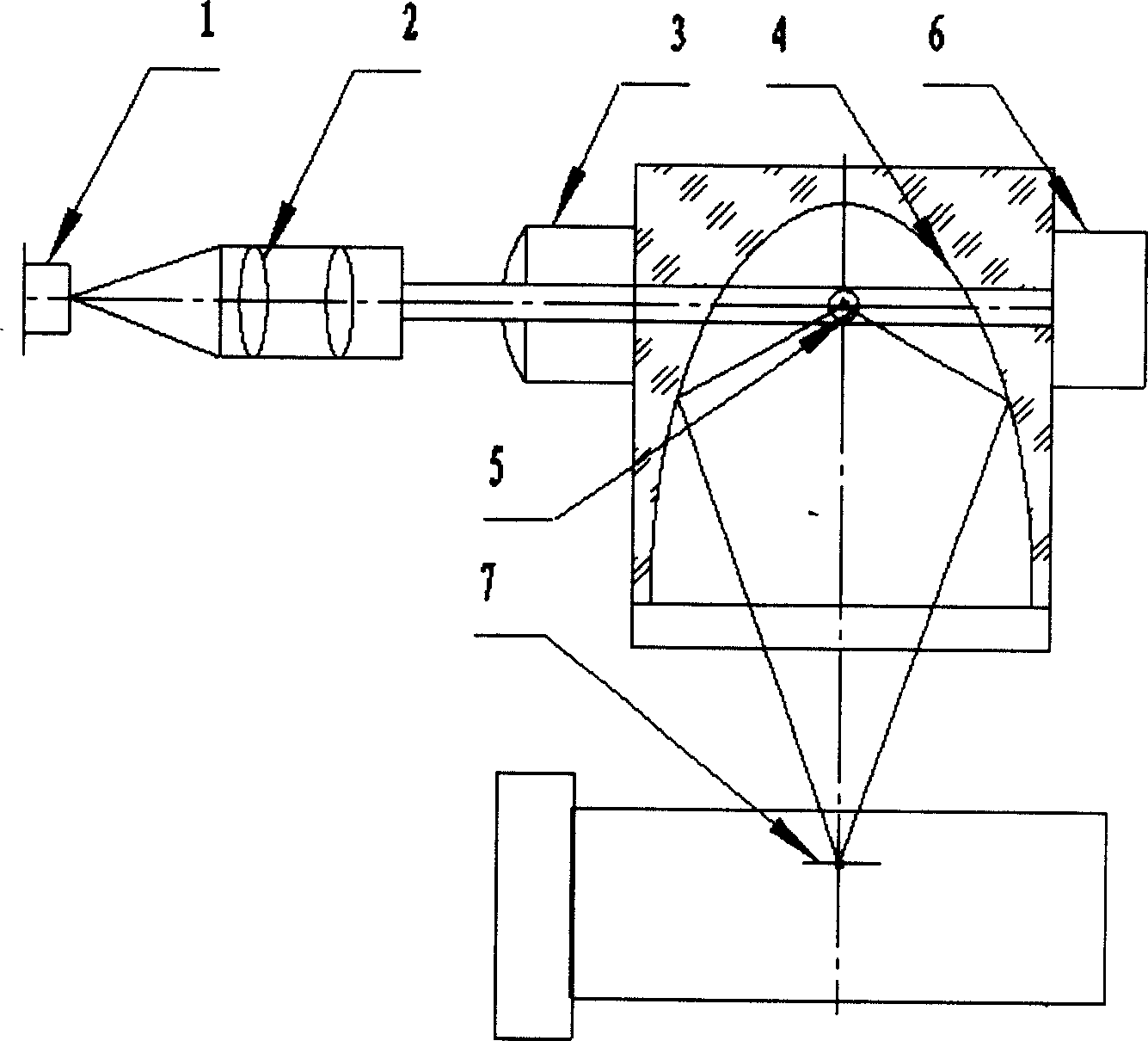
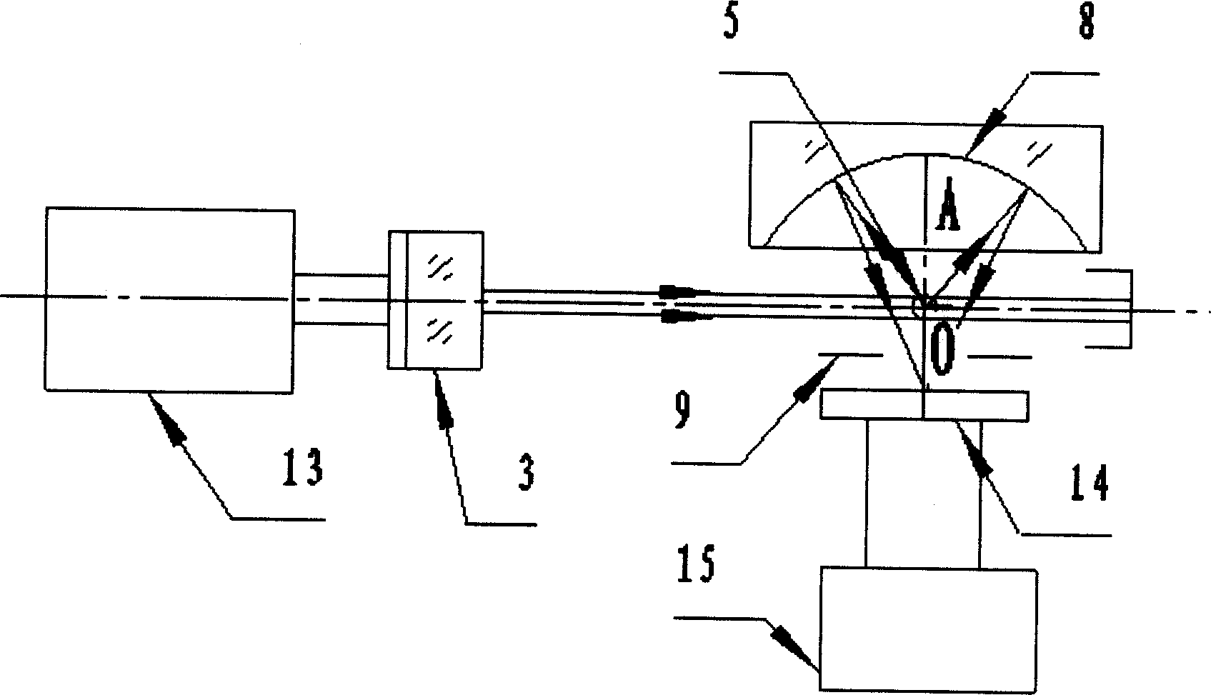
[0037] see figure 2 and image 3 . figure 2 and image 3 It is a structural schematic diagram of the laser dust particle counter miniature optical sensor of the present invention, by figure 2 and image 3 It can be seen that the micro optical sensor of the laser dust particle counter of the present invention is a right-angle scattering optical system, including an illumination system, a scattered light collection system, an air system and a preamplification circuit. The illumination system consists of a laser light source assembly 13 , a cylindrical mirror 3 and an optical trap 6 . The laser light source assembly 13 emits a collimated laser beam, which is one-dimensionally focused on the photosensitive area 5 by the cylindrical mirror 3, and the focal line is located in the plane formed by the optical axis of the illumination system and the optical axis of the scattered light collection system, and is perpendicular to the airflow direction . The laser beam enters the ...


PUM

PropertyMeasurementUnit
lengthaaaaaaaaaa
particle diameteraaaaaaaaaa
reflectanceaaaaaaaaaa

Abstract

A micro optical sensor of laser dust particle counter, which is characterized by its components, which comprises the following: there is cylinder mirror, spherical mirror and light trap located orderly in the direction of light beam of laser source components. The spherical mirror is located in the right side of the cylinder mirror and light-sensitive area and that of light-electricity detector are located on both sides around the sphere center of spherical mirror, which satisfies the image relationship of geometry optics; vision diaphragm which is suited for the shape of light sensitive-area is located in front of light-electricity detector; the light-electricity detector employs photoelectric diode of high sensitivity or micro photoelectric multiplier tube sealed with metal; A band pass preposition enlarging circuit is fixed in the shell of scatter body of optics sensor with the same width of pulse frequency of scattering light.

Description

Technical field: [0001] The invention relates to cleanliness testing equipment, in particular to a micro optical sensor for a laser dust particle counter. Background technique: [0002] In the prior art, the technical solution adopted by the optical sensor of the laser dust particle counter, such as the utility model patent "optical sensor of the dust particle counter" (Patent No. for ZL94239551.4), please refer to figure 1 . It adopts a right-angle scattering optical system structure, and the optical axis of the illumination system, the optical axis of the scattered light collection system and the axis of the gas path system intersect at the center of the light sensitive area and are perpendicular to each other. The illumination system wherein adopts laser diode 1 as light source, and the divergent light beam that laser diode 1 sends is collimated by the collimating mirror 2 that is placed on the right side of laser diode 1 and the cylindrical mirror 3 that is placed on t...

Claims


Application Information

Patent Timeline
Patent Type & Authority Applications(China)
IPC IPC(8): G01N15/14
Inventor 黄惠杰梁春雷任冰强赵永凯杜龙龙
Owner 上海镭慎光电科技有限公司
Why Eureka
Try Eureka