Alkali metal-sulfur secondary battery containing a nano sulfur-loaded cathode and manufacturing method

a technology of nano sulfur and secondary batteries, which is applied in the manufacture of final products, cell components, electrochemical generators, etc., can solve the problems of state-of-the-art li-ion batteries that have yet to meet cost and performance targets, internal short circuit and explosion, and achieve low electric and ionic conductivities, simple, cost-effective, and easy-to-implement effects

Active Publication Date: 2020-05-12
GLOBAL GRAPHENE GRP INC
View PDF7 Cites 1 Cited by
  • Summary
  • Abstract
  • Description
  • Claims
  • Application Information

AI Technical Summary

Benefits of technology

[0025]The present invention provides an alkali metal-sulfur cell (e.g. lithium-sulfur cell, sodium-sulfur cell, and potassium-sulfur cell). Such a battery cell contains an ultra-thin sulfur (S) coating layer or ultra-small small S particles (<2.0 nm) in a graphite or carbon material-based cathode having a large proportion of S (the cathode active material) relative to the supporting host (graphite or carbon material structure). The ultra-thin dimensions also enable high storing / releasing rates of alkali metal ions (Li+, Na+, and / or K+) and, hence, exceptional rate capability or power density.

Problems solved by technology

Unfortunately, upon repeated charges / discharges, the lithium metal resulted in the formation of dendrites at the anode that ultimately grew to penetrate through the separator, causing internal shorting and explosion.
Although lithium-ion (Li-ion) batteries are promising energy storage devices for electric drive vehicles, state-of-the-art Li-ion batteries have yet to meet the cost and performance targets.
However, the current Li-sulfur cells reported by industry leaders in sulfur cathode technology have a maximum cell specific energy of 250-400 Wh / kg (based on the total cell weight), which is far below what is possible.
In summary, despite its considerable advantages, the Li—S cell is plagued with several major technical problems that have thus far hindered its widespread commercialization:(1) Conventional lithium metal cells still have dendrite formation and related internal shorting issues.(2) Sulfur or sulfur-containing organic compounds are highly insulating, both electrically and ionically.
Various carbon-sulfur composites have been utilized for this purpose, but only with limited success owing to the limited scale of the contact area.
This is mainly due to the high solubility of the lithium polysulfide anions formed as reaction intermediates during both discharge and charge processes in the polar organic solvents used in electrolytes.
In addition, the solid product that precipitates on the surface of the positive electrode during discharge becomes electrochemically irreversible, which also contributes to active mass loss.(4) More generally speaking, a significant drawback with cells containing cathodes comprising elemental sulfur, organosulfur and carbon-sulfur materials relates to the dissolution and excessive out-diffusion of soluble sulfides, polysulfides, organo-sulfides, carbon-sulfides and / or carbon-polysulfides (hereinafter referred to as anionic reduction products) from the cathode into the rest of the cell.
This process leads to several problems: high self-discharge rates, loss of cathode capacity, corrosion of current collectors and electrical leads leading to loss of electrical contact to active cell components, fouling of the anode surface giving rise to malfunction of the anode, and clogging of the pores in the cell membrane separator which leads to loss of ion transport and large increases in internal resistance in the cell.
Some interesting cathode developments have been reported recently to contain lithium polysulfides; but, their performance still fall short of what is required for practical applications.
However, the fabrication of the proposed highly ordered meso-porous carbon structure requires a tedious and expensive template-assisted process.
It is also challenging to load a large proportion of sulfur into these meso-scaled pores using a physical vapor deposition or solution precipitation process.
But, this method is incapable of creating a large proportion of ultra-small S particles on GO surfaces (i.e. typically <66% of S in the GO-S nanocomposite composition).
It may be noted that the highest achievable specific capacity of 1,100 mAh / g represents a sulfur utilization efficiency of only 1,100 / 1,675=65.7% even at such a low charge / discharge rate (0.02 C means completing the charge or discharge process in 1 / 0.02=50 hours; 1 C=1 hour, 2 C=½ hours, and 3 C=⅓ hours, etc.) Further, such a S-GO nanocomposite cathode-based Li—S cell exhibits very poor cycle life, with the capacity typically dropping to less than 60% of its original capacity in less than 40 charge / discharge cycles.
Such a short cycle life makes this Li—S cell not useful for any practical application.
Unfortunately, this method does not appear to be capable of producing S particles less than 40 nm.
The resulting Li—S cell exhibits very poor cycle life (a 50% decay in capacity after only 50 cycles).
Again, this implies that a large proportion of S did not contribute to the lithium storage, resulting in a low S utilization efficiency.
These S particles prevent graphene sheets from contacting each other, making it impossible for otherwise conducting graphene sheets to form a 3-D network of electron-conducting paths in the cathode.
This unintended and unexpected outcome is another reason why these prior art Li—S cells have performed so poorly.
Sodium metal (Na) and potassium metal (K) have similar chemical characteristics to Li and the sulfur cathode in room temperature sodium-sulfur cells (RT Na—S batteries) or potassium-sulfur cells (K—S) face the same issues observed in Li—S batteries, such as: (i) low active material utilization rate, (ii) poor cycle life, and (iii) low Coulombic efficiency.
Again, these drawbacks arise mainly from insulating nature of S, dissolution of S and Na or K polysulfide intermediates in liquid electrolytes (and related Shuttle effect), and large volume change during charge / discharge.
It may be noted that in most of the open literature reports (scientific papers) and patent documents, scientists or inventors choose to express the cathode specific capacity based on the sulfur or lithium polysulfide weight alone (not the total cathode composite weight), but unfortunately a large proportion of non-active materials (those not capable of storing lithium, such as conductive additive and binder) is typically used in their Li—S cells.

Method used


Image

  • Alkali metal-sulfur secondary battery containing a nano sulfur-loaded cathode and manufacturing method
  • Alkali metal-sulfur secondary battery containing a nano sulfur-loaded cathode and manufacturing method
  • Alkali metal-sulfur secondary battery containing a nano sulfur-loaded cathode and manufacturing method

Examples


example 1

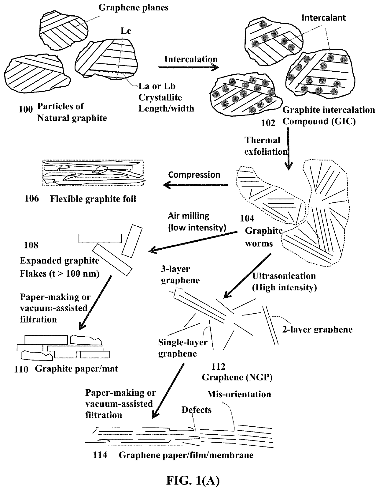
of Graphite to Produce Graphite Particles Having Expanded d Spacing

[0132]Natural flake graphite, nominally sized at 45 μm, provided by Asbury Carbons (405 Old Main St., Asbury, N.J. 08802, USA) was milled to reduce the size to approximately 14 μm (Sample 1a). The chemicals used in the present study, including fuming nitric acid (>90%), sulfuric acid (95-98%), potassium chlorate (98%), and hydrochloric acid (37%), were purchased from Sigma-Aldrich and used as received. Graphite oxide (GO) samples were prepared according to the following procedure:

[0133]Sample 1A: A reaction flask containing a magnetic stir bar was charged with sulfuric acid (176 mL) and nitric acid (90 mL) and cooled by immersion in an ice bath. The acid mixture was stirred and allowed to cool for 15 min, and graphite (10 g) was added under vigorous stirring to avoid agglomeration. After the graphite powder was well dispersed, potassium chlorate (110 g) was added slowly over 15 min to avoid sudden increases in temper...

example 2

and Intercalation of Various Graphitic Carbon and Graphite Materials

[0137]Samples 2A, 2B, 2C, and 2D were prepared according to the same procedure used for Sample 1B, but the starting graphite materials were pieces of highly oriented pyrolytic graphite (HOPG), graphite fiber, graphitic carbon nano-fiber, and spheroidal graphite, respectively. Their final inter-planar spacings are 6.6 Å, 7.3 Å, 7.3 Å, and 6.6 Å, respectively. Their un-treated counterparts are referred to as Sample 2a, 2b, 2c, and 2d, respectively.

example 3

on of Graphite Oxide from Natural Graphite and Needle Coke Using a Modified Hummers' Method

[0138]Graphite oxide (Sample 3A) was prepared by oxidation of natural graphite flakes (original size of 200 mesh, from Huadong Graphite Co., Pingdu, China, milled to approximately 15.mu.m, referred to as Sample 3a) and needle coke with sulfuric acid, sodium nitrate, and potassium permanganate according to the method of Hummers [U.S. Pat. No. 2,798,878, Jul. 9, 1957]. Anisotropic needle coke has a fully developed needle-shape texture of optical anisotropy. Volatile species of the raw coke was estimated to be around 5 wt. %.

[0139]In this example, for every 1 gram of graphite or needle coke, we used a mixture of 22 ml of concentrated sulfuric acid, 2.8 grams of potassium permanganate, and 0.5 grams of sodium nitrate. The graphite flakes were immersed in the mixture solution and the reaction time was approximately one hour at 35.degree. C. It is important to caution that potassium permanganate sho...


PUM

PropertyMeasurementUnit
specific energyaaaaaaaaaa
energy densitiesaaaaaaaaaa

Abstract

A rechargeable alkali metal-sulfur cell selected from lithium-sulfur cell, sodium-sulfur cell, or potassium-sulfur cell The alkali metal-sulfur cell comprises an anode active material layer, an optional anode current collector supporting the anode active material layer, a cathode active material layer, an electrolyte with an optional porous separator layer in ionic contact with the anode active material layer and the cathode active material layer, and an optional cathode current collector supporting the cathode active material layer, wherein the cathode active material layer contains a graphite or carbon material having expanded inter-graphene planar spaces with an inter-planar spacing d002 from 0.43 nm to 2.0 nm, as measured by X-ray diffraction, and 1%-95% by weight of sulfur or a metal polysulfide residing in these expanded inter-graphene planar spaces. This battery exhibits an excellent combination of high sulfur content, high sulfur utilization efficiency, high energy density, and long cycle life.

Description

FIELD OF THE INVENTION[0001]The present invention provides a unique cathode composition and structure in a secondary or rechargeable alkali metal-sulfur battery, including the lithium-sulfur battery, sodium-sulfur battery, and potassium-sulfur battery. The lithium-sulfur battery can include the lithium metal-sulfur battery (having lithium metal as the anode active material and sulfur as the cathode active material) and the lithium ion-sulfur battery (e.g. Si or graphite as the anode active material and sulfur as the cathode active material). The sodium-sulfur battery can include the sodium metal-sulfur battery (having sodium metal as the anode active material and sulfur as the cathode active material) and the sodium ion-sulfur battery (e.g. hard carbon as the anode active material and sulfur as the cathode active material).BACKGROUND[0002]Rechargeable lithium-ion (Li-ion) and lithium metal batteries (including Li-sulfur and Li metal-air batteries) are considered promising power sour...

Claims


Application Information

Patent Timeline
Patent Type & Authority Patents(United States)
IPC IPC(8): H01M4/38H01M10/052H01M4/62H01M4/58H01M4/02
CPCH01M4/381H01M4/382H01M4/38H01M4/625H01M4/5815H01M10/052H01M2004/028Y02E60/10Y02P70/50H01M10/054H01M4/13H01M4/136
Inventor ZHAMU, ARUNAJANG, BOR Z.
Owner GLOBAL GRAPHENE GRP INC
Why Eureka
Try Eureka