Adhesion method and electronic component

a technology of adhesive and heat conductive adhesive, which is applied in the directions of adhesive additives, semiconductor/solid-state device details, transportation and packaging, etc., can solve the problems of shortening the life of electronic components, destroying composing materials, and not presenting a sufficient conductivity, so as to improve heat conduction, effective dissipation of heat generated, and excellent radiation

Inactive Publication Date: 2001-06-21
POLYMATECH CO LTD
View PDF0 Cites 229 Cited by
  • Summary
  • Abstract
  • Description
  • Claims
  • Application Information

AI Technical Summary

Benefits of technology

0010] In the purpose of solving the aforementioned problems, the present invention provides an adhesion method of heat conductive for effectively dissipating heat generated from semiconductor device, power source, light source or other components used for the electric products, and an electronic component excellent in radiation.
0011] For this effect, the present invention provides an adhesion method of improving the heat conduction in a fixed direction by using a heat conductive adhesive made by blending boron nitride powder and adhesive polymer and adhering by orienting boron nitride powder in the heat conductive adhesive to the fixed direction under the magnetic atmosphere and an electronic component.

Problems solved by technology

However, the boron nitride powder have a heat conductivity in the flake shape thickness direction smaller than it heat conductivity in the surface direction; therefore, an adhesive blending simply boron nitride powder in a polymer could not present a sufficient conductivity as its surface direction is charged in parallel to the thickness direction in the adhesive layer after adhesion.
In other words, as a adhesion method having a good electric insulation and high heat conductivity has not been developed, a considerable heat generation from semiconductor device or other electric components accelerated the electro-chemical migration or corrosion of wiring or pad portions, the generated heat stress provoked cracking or destruction of composing material, the interface of composing material junctions was peeled off, or other troubles happened in a way to shorten the life of electronic components.

Method used


Image

  • Adhesion method and electronic component
  • Adhesion method and electronic component
  • Adhesion method and electronic component

Examples


example 1

[0033] A heat conductive adhesive A is prepare by blending 40 weight parts of hexagonal crystalline system flake form boron nitride powder (made by Showa Denko Co., Ltd. UHP-S1 average particle diameter 1 to 2 .mu.m) treated with aminosilane base coupling agent and 100 weight parts of bisphenol F type epoxy resin containing amine base hardener as adhesive polymer, and degassing in the vacuum.

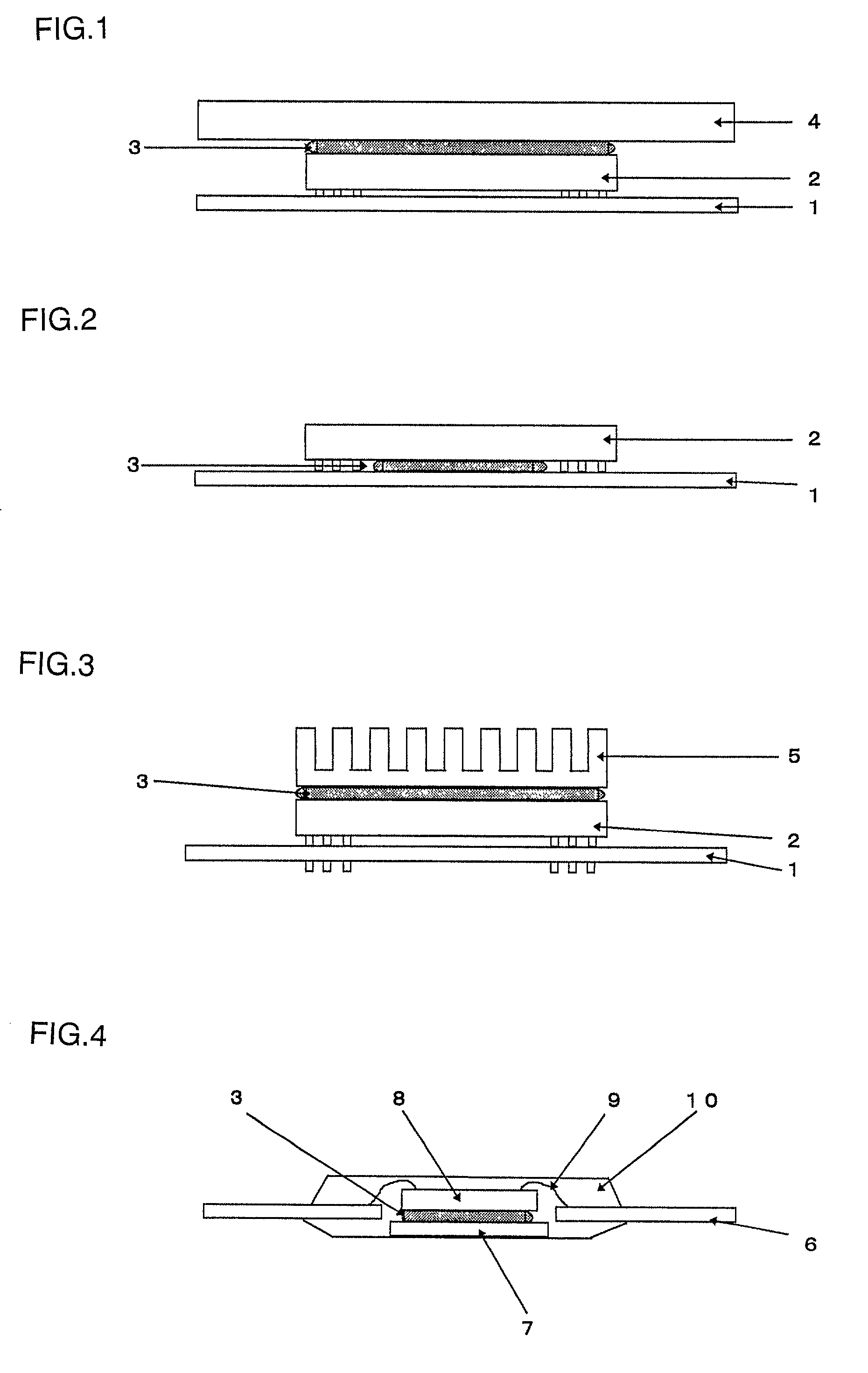
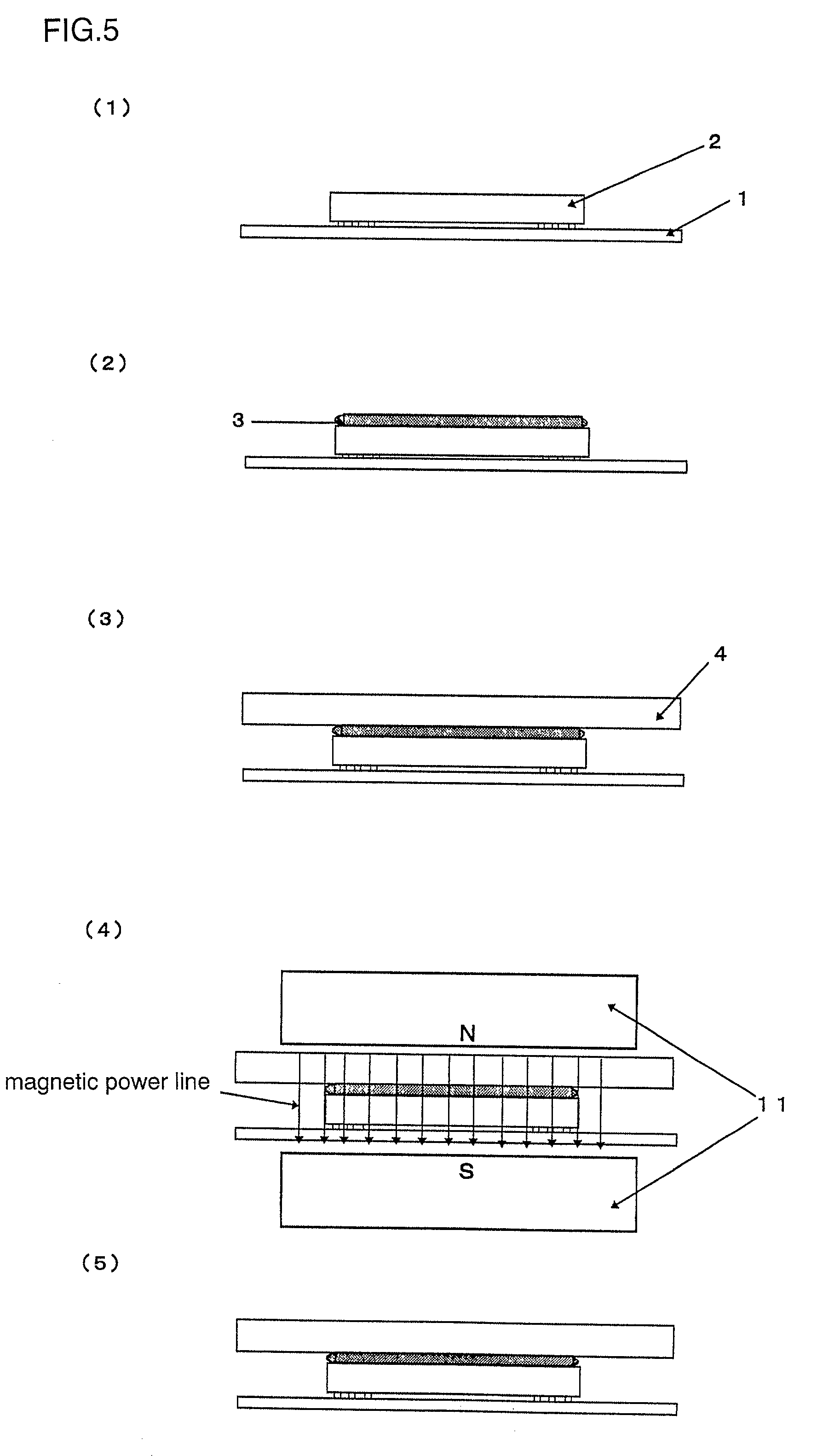
[0034] The heat conductive adhesive A is applied with a dispenser to a ball grid array type semiconductor package 2 implemented on a PCB 1 describe in FIG. 5(1) (FIG. 5(2)). A radiator 1 is disposed and pressed on the upper portion of the heat conductive adhesive A as shown in FIG. 5(3), and an electronic component (FIG. 5(5)) is prepared by heat setting the heat conductive adhesive A in a magnetic field atmosphere where N pole and S pole of an permanent magnet 11 of flux density 0.6 tesla are opposed as shown in FIG. 5(4).

[0035] The apparatus is turned on to measure the heat resistance after 6 ...

example 2

[0038] A heat conductive adhesive B is prepare by blending 80 weight parts of hexagonal crystalline system flake form boron nitride powder (made by Showa Denko Co., Ltd. UHP-S1 average particle diameter 1 to 2 .mu.m) and 100 weight parts of added type liquid silicon rubber (made by GE Toshiba Silicon, TSE3331) as adhesive polymer, and degassing in the vacuum.

[0039] The heat conductive adhesive B is applied with a dispenser to a ball grid array type semiconductor package 2 implemented on a PCB 1 describe in FIG. 5(1) (FIG. 5(2)) as in the Example 1. A radiator 1 is disposed and pressed on the upper portion of the heat conductive adhesive B as shown in FIG. 5(3), and an electronic component (FIG. 5(5)) is prepared by heat setting the heat conductive adhesive B in a magnetic field atmosphere where N pole and S pole of an electromagnetic magnet 11 of flux density 2 tesla are opposed as shown in FIG. 5(4).

[0040] The apparatus is turned on to measure the heat resistance after 6 minutes, o...

example 3

[0043] A heat conductive adhesive C is prepare by blending 120 weight parts of hexagonal crystalline system fine particle form boron nitride powder (made by Denki Kagaku Kogyo Co., Ltd. SP-1 average particle diameter 0.6 .mu.m) agent and 100 weight parts of thermo-setting polyimide (made by Ube Kosan Co., Ltd. Yupitite UPA-83), and degassing in the vacuum.

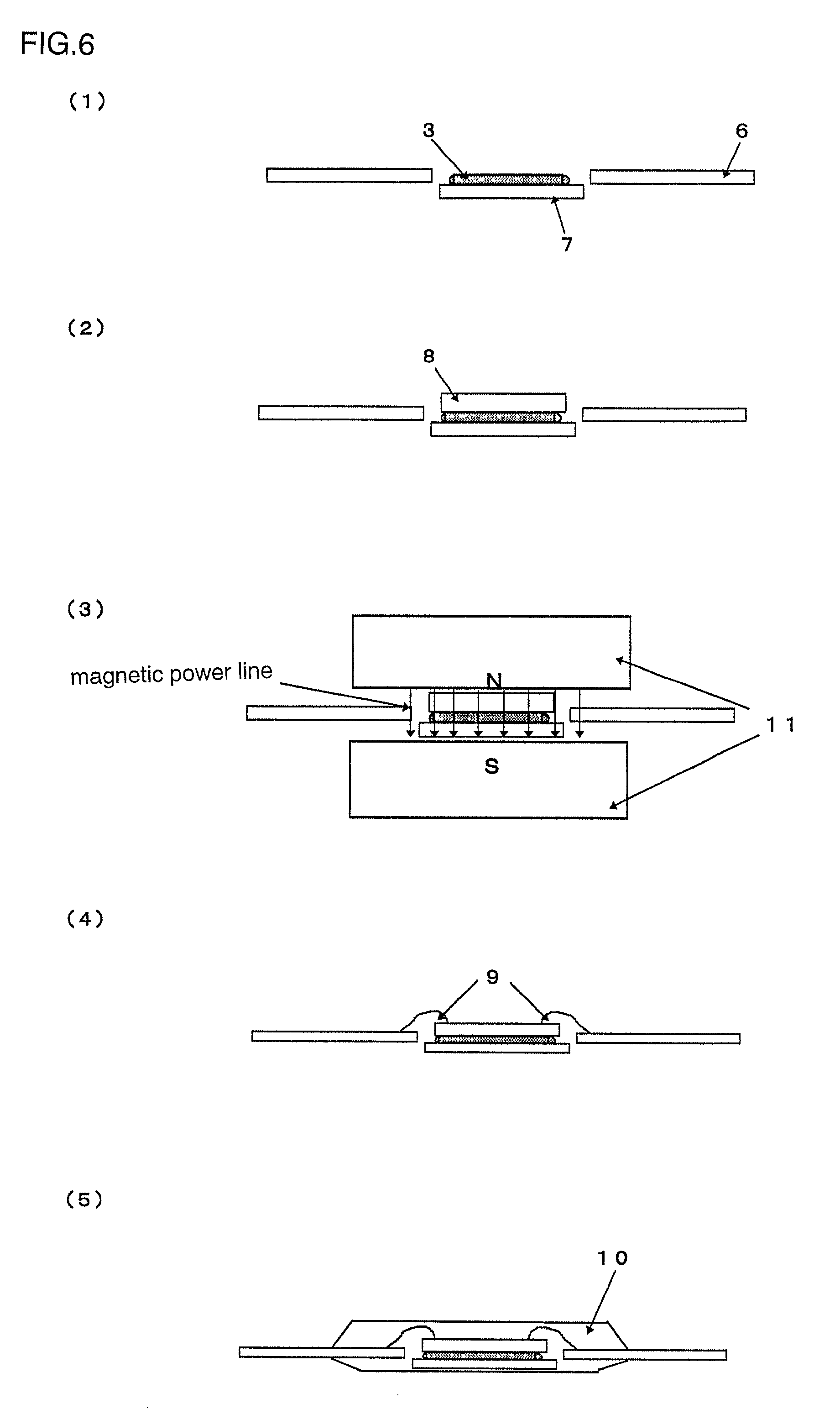
[0044] The heat conductive adhesive C is screen printed on a die pad 7 of a lead frame 6 describe in FIG. 6(1) (FIG. 6(2)). A semiconductor chip 8 is disposed and pressed on the upper portion of the heat conductive adhesive C as shown in FIG. 6(2), and the heat conductive adhesive C is heat set in a magnetic field atmosphere where N pole and S pole of an electromagnetic magnet 11 of flux density 2 tesla are opposed as shown in FIG. 6(3). An electronic component(FIG. 6(5)) is manufactured by connecting an electrode portion of the semiconductor chip 8 and a lead portion of the lead frame 11 by a bonding wire 9 (FIG. 6(4)) and by tran...


PUM

PropertyMeasurementUnit
average primary diameteraaaaaaaaaa
diameteraaaaaaaaaa

Abstract

The present invention provides an adhesion method of improving the heat conduction in a fixed direction by using a heat conductive adhesive made by blending boron nitride powder and adhesive polymer and adhering by orienting boron nitride powder in the heat conductive adhesive to the fixed direction under the magnetic atmosphere and an electronic component for effectively dissipating heat generated from semiconductor device 2, power source 4, light source or other components used for the electric products, and an electronic component excellent in radiation.

Description

BACKGROUND OF THE INVENTION[0001] 1. Technical Field of the Invention[0002] The present invention concerns an adhesion method of heat conductive adhesive requiring high heat conductivity and an electronic component. More particularly, it concerns an adhesion method of heat conductive adhesive for effectively dissipating heat generated from semiconductor device, power source, light source or other components used for the electric products, and an electronic component excellent in radiation.[0003] 2. Prior Art[0004] Conventionally, heat conductive adhesives having adhesive polymer as matrix have been used for bonding a head generating semiconductor device or electronic component with a heat radiating conductive member. Silver, copper, gold, aluminum, or other metals and alloys having a good heat conductivity, or aluminum oxide, magnesium oxide, silicon oxide, boron nitride, aluminum nitride, silicon nitride, silicon carbide or other ceramics, carbon black, graphite, diamond or various...

Claims


Application Information

Patent Timeline
Patent Type & Authority Applications(United States)
IPC IPC(8): C01B21/064C09J5/00C09J9/00H01L23/40C09J11/04C09J201/00H01L21/58
CPCC09J5/00C09J9/00C09J11/04H01L24/29H01L24/83H01L2224/16H01L2224/32245H01L2224/48091H01L2224/48247H01L2224/73253H01L2224/73265H01L2224/83192H01L2224/83194H01L2224/8385H01L2224/92247H01L2924/01004H01L2924/01005H01L2924/01012H01L2924/01013H01L2924/01027H01L2924/01029H01L2924/01032H01L2924/01033H01L2924/01047H01L2924/01074H01L2924/01078H01L2924/01079H01L2924/01082H01L2924/07802H01L2224/29H01L2224/2919H01L2924/01006H01L2924/01019H01L2924/0665H01L2224/2929H01L2224/29339H01L2224/29344H01L2224/29347H01L2224/29355H01L2224/29369H01L2224/29386H01L2224/29393H01L24/75H01L2924/00013H01L2924/351H01L2924/181Y10T428/25H01L24/73H01L2924/00014H01L2924/00H01L2924/00012H01L2924/0503H01L2924/05432H01L2924/0532H01L2924/05032H01L2924/05442H01L2924/04642H01L2924/3512H01L2224/29099H01L2224/29199H01L2224/29299
Inventor MASAYUKI, TOBITATATEDA, SHINYAKIMURA, TSUNEHISAYAMATO, MASAHUMI
Owner POLYMATECH CO LTD
Why Eureka
Try Eureka