Fuel cell membrane electrode assemblies with improved power outputs and poison resistance

a fuel cell membrane electrode and power output technology, applied in the direction of cell components, electrochemical generators, vacuum evaporation coating, etc., can solve the problems of power output loss, initial cost, and longening the operational li

Inactive Publication Date: 2001-10-25
WL GORE & ASSOC INC
View PDF0 Cites 37 Cited by
  • Summary
  • Abstract
  • Description
  • Claims
  • Application Information

AI Technical Summary

Benefits of technology

[0041] depositing onto at least one of the assembly elements a zone consisting essentially of at least two second catalytically active metals having a zone thickness of about 3 angstroms to about 5,000 angstroms, wherein the zone deposition is (i) a direct deposition onto the assembly element, or (ii) an indirect deposition onto the assembly element wherein the deposited zone is first deposited onto a substrate and then transferred from the substrate onto the assembly element, and
[0042] optionally, assembling the membrane electrode assembly from the assembly elements.
[0043] The advantages of this invention, in its multiple embodiments, are numerous. In addition to improved power output with better catalyst utilization and poison resistance, a further important advantage is that multiple methods can be used to prepare the structures, and that these multiple methods can be tailored to different commercial applications. More precise design and control is now possible. Good integration between the membrane and electrode, and between membrane, cathode, and anode has been achieved. Also noteworthy are that the zone of catalyst metal does not substantially upset the water balance of the fuel cell system, that the invention can be applied to different fuel cell reactants, and that process scalability has been demonstrated. Different deposition methods can be used including electron beam physical vapor deposition and multi-target sputtering. Surprisingly, mixtures of catalysts can have both improved poison resistance and improved power output compared to a single catalyst. Finally, catalyst zones consist essentially of catalytically active metals for which organized, whisker-like substrates are not needed to support the metals, and which provide for good interfacial contact between catalytically active metal and ion conductive material.
[0044] In sum, the invention responds to the market demands to be commercially realistic.

Problems solved by technology

Despite improvements in fuel cell technology, however, long felt needs generally exist to increase power output, reduce initial cost, improve water management, and lengthen operational lifetime.
Such reduction, however, generally results in power output loss which blocks commercialization efforts.
Fuel cell systems are complex because the reaction is believed localized at a three-phase boundary between ionically conducting membrane, gas, and carbon supported catalyst.
However, the additional ionic conductor can introduce extra cost, especially when perfluorinated conductors are used, and can increase the complexity of electrolyte water management, all important to commercialization.
However, long operational lifetimes are particularly difficult to achieve with lower catalyst loadings, and catalyst poisoning can occur.
Also, catalyst particle size may be unstable and increase by agglomeration or sintering.
However, sputtered layers thinner than 500 angstroms were not reported, possibly because of the difficulty in making uniform thinner layers.
Moreover, the concentration of catalyst approach may not be suitable for other types of electrodes and deposition techniques and may upset water balance.
Further, testing often is not carried out under commercial conditions.
Particularly poor performance was reported for electrodes in which all of the catalyst metal was in the form of a sputtered film.
In sum, it is recognized that mere vapor depositing an allegedly thin layer of catalyst onto the electrode does not guarantee a suitable MEA for commercial applications, and in general, industry has not accepted this approach as realistic. . According to the Srinivasan article noted above, for example, sputtering may not be economically feasible compared with wet chemical deposition methods.
Combinations of properties, which are vital for commercialization, can be difficult to achieve without this integrated approach.
Finally, another problem which can arise and block commercialization is catalyst poisoning which is caused by impurities such as carbon monoxide (CO) in the reactants.
For example, when hydrogen fuel is generated by hydrocarbon reforming, CO can be co-generated which is expensive to remove, particularly when the CO level in hydrogen is reduced to below 100 ppm.
Poisoning is especially problematic in PEMFCs which have low catalyst loadings and which employ the single metal platinum.
Although attempts to mitigate CO poisoning have been reported, they generally have been unsuccessful and have resulted in reduced power.
However, ink methods can be difficult to control precisely, and some vacuum methods can be expensive and cumbersome, particularly for thin film deposition.
However, this article reports problems in obtaining consistent results and reproducible data with bimetallic systems.
However, there is no concentration of the catalytically active metal at the membrane-electrode interface.
Rather, the layered structures described are not concentrated and would be expected to have relatively poor catalytic efficiency.
Moreover, the vacuum-deposited membrane is excessively thin and would not generally be a suitable fuel cell barrier in practical applications.
Finally, no experiments are reported in this patent on the performance of the membrane electrode assembly, particularly under commercially realistic conditions.
Although experimental data are reported in these patents, no experimental data are reported for a working membrane electrode assembly or fuel cell.
Also, polymer electrolyte membrane fuel cells are not taught or suggested.
These patents, however, do not teach or suggest catalyst in a form which is not intimately joined or bonded to the whisker support, which is generally non-conductive.
Also, these patents teach that use of ionically conductive polymer in the electrode is undesirable, and that maximum contact between the catalyst and the ionically conductive material is not important.
In general, therefore, the prior art apparently does not teach, demonstrate, or even suggest fuel cell technology which is suitable for the current or next generation commercial demands.

Method used


Image

  • Fuel cell membrane electrode assemblies with improved power outputs and poison resistance
  • Fuel cell membrane electrode assemblies with improved power outputs and poison resistance
  • Fuel cell membrane electrode assemblies with improved power outputs and poison resistance

Examples


second embodiment

[0164] In alternative embodiments, however, which are now described, the electrode of the membrane-electrode combination is substantially free of first catalytically active metal, and the zone of second catalytically active metal includes at least two different catalytically active metals which helps improve resistance to poisoning. Hence, the primary, and preferably essentially all, catalytic activity is from the zone. These alternative embodiments, wherein the electrode is substantially free of first catalytically active metal, are called collectively for purposes herein "THE SECOND EMBODIMENT" and are described further hereinbelow.

[0165] In the second embodiment, preferably, the amount of first catalytically active metal is minimized so that the electrode is substantially free of first catalytically active metal, and preferably, totally free. More specifically, catalytic loading for the first catalytically active metal can be less than about 0.1 mg / cm.sup.2, and preferably less t...

first embodiment

[0170] Deposition methods are noted above in the description of the first embodiment and include sputtering and thermal evaporation. In a multi-metallic physical vapor deposition, such as electron beam physical vapor deposition, separate metal sources of about 99.9 wt. % platinum and about 99.9 wt. % ruthenium are evaporated. Preferably, for a bimetallic mixture of these metals, the atomic ratio of each metal is about 1:1. Simultaneous or sequential physical vapor deposition methods can be used. In simultaneous deposition, two different sources are used and simultaneously evaporated together, and the vapor composition is controlled by each source's relative evaporation rate. In sequential deposition, each metal is separately evaporated from its source in a toggle-like manner and deposited onto the chosen substrate in alternate thin layers. Alloying of the metals can be encouraged when the layers are thin enough. In addition, ion bombardment treatment such as, for example, ion beam a...

example 1

[0191] Example 1 illustrates the indirect method wherein the zone of second catalytically active metal is first deposited onto a substrate before transfer from the substrate to the membrane or electrode.

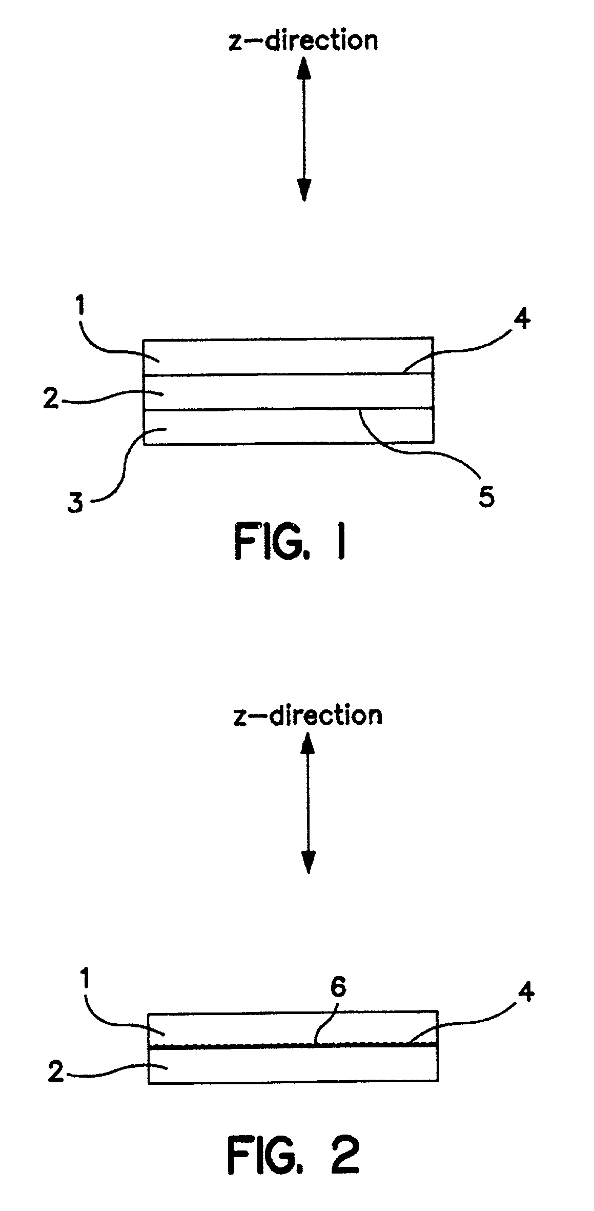
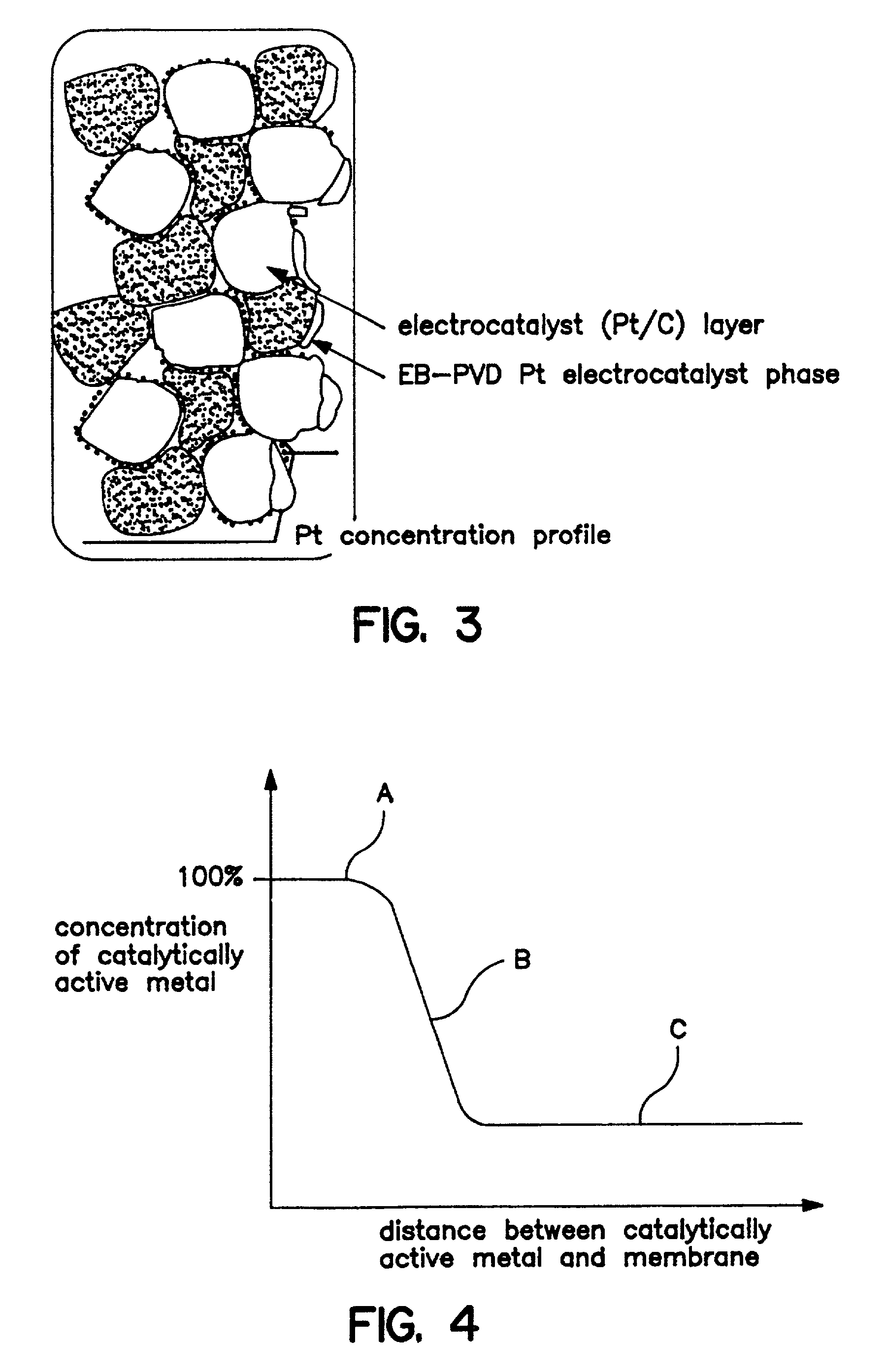
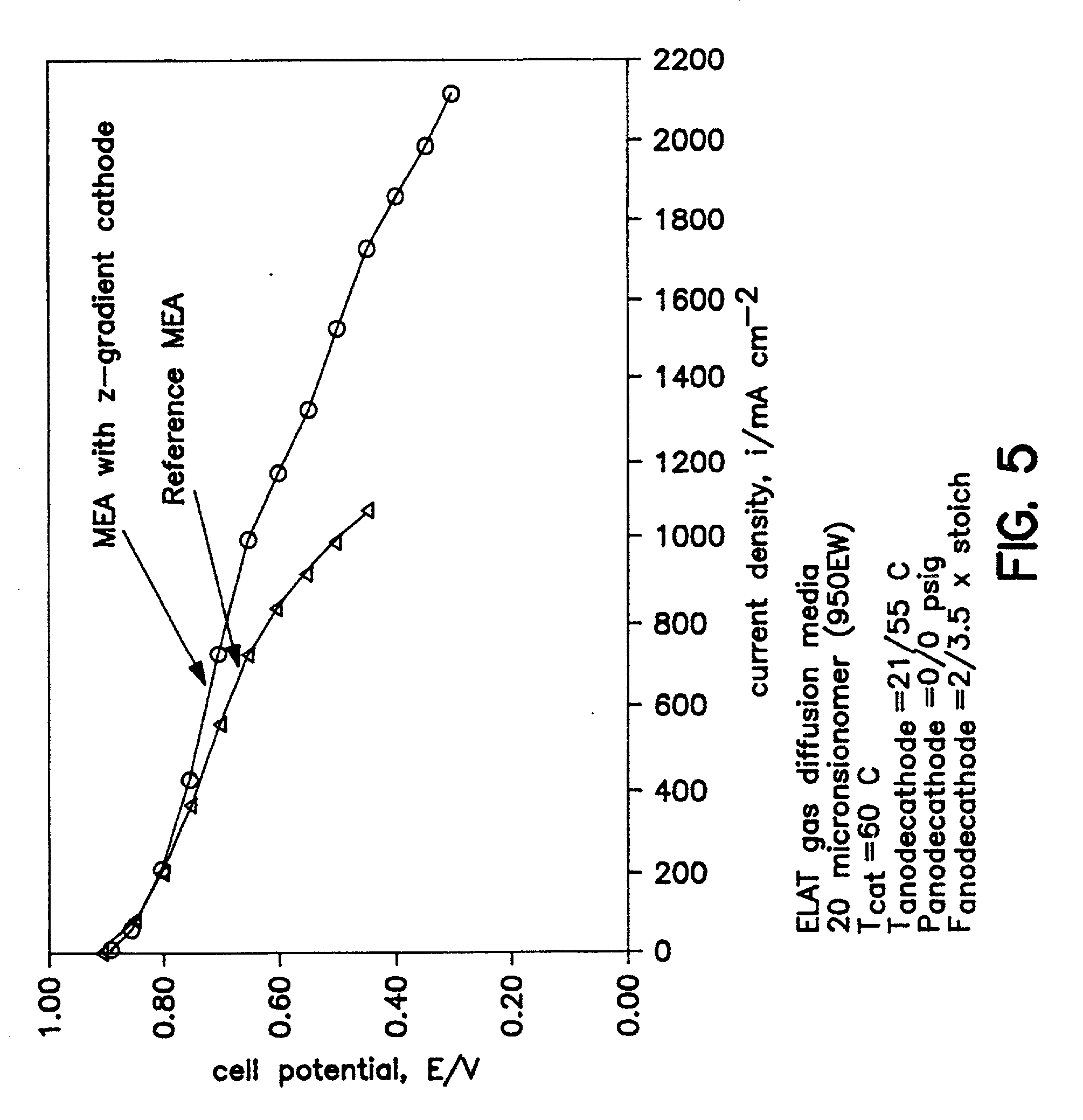
[0192] A 50 .ANG. platinum coating zone (0.01 mg / cm.sup.2) was deposited at 1 .ANG. / sec onto a skived PTFE substrate backing by EB-PVD. The catalyst zone was then transferred onto the membrane by the decal method leaving the 50 .ANG. catalyst zone bonded to one side of the membrane and positioned centrally. The area of the membrane demarcated by the transferred catalyst is the active area. A catalyzed electrode (0.3 mg Pt / cm.sup.2) was attached to each side of the catalyzed membrane also using the decal method, so as to overlay the active area. Therefore, one side of the MEA had a z-gradient zone of platinum at the membrane / electrode interface.

[0193] The prepared MEAs with 25 cm.sup.2 active areas were each loaded between gaskets in a 25 cm.sup.2 active area fuel cell test fixture or...


PUM

PropertyMeasurementUnit
thicknessaaaaaaaaaa
thicknessaaaaaaaaaa
thicknessaaaaaaaaaa

Abstract

An electrode-membrane combination for use in a fuel cell and providing improved power outputs and resistance to poisoning. Multiple embodiments are described which generally involve use of a vapor deposited zone or layer of one or more catalytically active metals. Vapor deposition can be carried out by, for example, sputtering or physical vapor deposition.

Description

[0001] This invention relates generally to fuel cell membrane electrode assemblies with improved power outputs. More particularly, these improved assemblies feature a relatively thin zone of one or more catalytically active metals at the membrane-electrode interface in addition to the catalytically active metal which also can be present in the electrode.BACKGROUND TO THE INVENTION[0002] Fuel cells continue to show great commercial promise throughout the world as an alternative to conventional energy sources. This commercial promise should continue to grow as energy shortages become more acute, environmental regulations become more stringent, and new fuel cell applications emerge. See, e.g. "FUEL CELLS", Encyclopedia of Chemical Technology, 4th Ed., Vol. 11, pp. 1098-1121. Strikingly, numerous automotive manufacturers have announced and continue to announce plans for mass production and retail sale of fuel cell-powered cars in the near future.[0003] Despite improvements in fuel cell ...

Claims


Application Information

Patent Timeline
Patent Type & Authority Applications(United States)
IPC IPC(8): C23C14/14H01M4/86H01M4/88H01M4/90H01M4/92H01M4/96H01M8/00H01M8/02H01M8/10
CPCH01M4/8642H01M8/1004H01M2300/0082Y02E60/521Y02E60/50
Inventor CAVALCA, CARLOS A.ARPS, JAMES H.MURTHY, MAHESH
Owner WL GORE & ASSOC INC
Why Eureka
Try Eureka